Wireless charging coil assembly and electric energy transmission system adopting assembly

A technology of wireless charging and coil assembly, which is applied in the direction of transformer/inductor coil/winding/connection, electrical components, transformer/inductor parts, etc., which can solve the problem of difficult alignment of transmitting coils, reduced coil transmission efficiency, and increased system complexity In order to achieve the effect of improving coil integration, large coupling coefficient and eliminating mutual inductance

Inactive Publication Date: 2017-07-14
SHANGHAI JIAO TONG UNIV
View PDF7 Cites 7 Cited by
  • Summary
  • Abstract
  • Description
  • Claims
  • Application Information

AI Technical Summary

Problems solved by technology

Generally, there is only one coil at the transmitting end and the receiving end of the coil with a common structure. If the corresponding circuit topology has two or more inductors, additional inductors need to be made, which increases the complexity of the system.
In addition, due to the charging process of electric vehicles, the receiving coil on the chassis of the car is not easy to align with the transmitting coil laid on the ground, and it is easy to shift
In this case, the coil transmission efficiency of the common structure will be further reduced

Method used


Image

  • Wireless charging coil assembly and electric energy transmission system adopting assembly
  • Wireless charging coil assembly and electric energy transmission system adopting assembly
  • Wireless charging coil assembly and electric energy transmission system adopting assembly

Examples


Embodiment Construction

[0023] The present invention will be described in detail below in conjunction with specific embodiments. The following examples will help those skilled in the art to further understand the present invention, but do not limit the present invention in any form. It should be noted that those skilled in the art can make several changes and improvements without departing from the concept of the present invention.

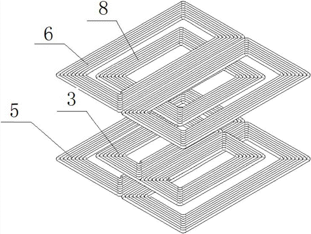
[0024] Such as Figure 1 ~ Figure 4 As shown, the wireless charging coil assembly of the present invention includes: a primary side main coil 5 , a primary side auxiliary coil 3 , a secondary side main coil 6 and a secondary side auxiliary coil 8 .

[0025] The first wireless charging ring unit (primary side) and the second wireless charging ring unit (secondary side) are symmetrical about a plane at an equal distance from the primary side and the secondary side. The primary-side auxiliary coil 3 is located in the center of the primary-side main coil 5 , and the length...


PUM


Abstract

The invention provides a wireless charging coil assembly. The wireless charging coil assembly comprises a first wireless charging coil unit and a second wireless charging coil unit, wherein the first wireless charging coil unit comprises a primary side main coil and a primary side secondary coil; the primary side secondary coil and the primary side main coil are connected in series; the second wireless charging coil unit comprises a secondary side main coil and a secondary side secondary coil; the secondary side secondary coil and the secondary side main coil are connected in series; and the first wireless charging coil unit and the second wireless charging coil unit are symmetrically arranged. Compared with the prior art, the wireless charging coil assembly has the following advantages: the primary side main coil and the secondary side main coil adopt a serial dual-rectangular structure having a shape as shown in the specification, so that the transmission efficiency of the coils is effectively improved; the primary side secondary coil and the secondary side secondary coil adopt a serial dual-rectangular structure having a shape as shown in the specification; and therefore, when the coils are used in a multi-inductor resonant circuit, mutual influence between a main inductor and a secondary inductor can be avoided under a condition that the integration degree of the coils is improved.

Description

technical field [0001] The invention relates to the technical field of wireless power transmission, in particular to a wireless charging coil assembly and a power transmission system using the same. Background technique [0002] In recent years, with the continuous development of power electronics technology, the efficiency and power of wireless charging systems have been continuously improved, and the application range has been continuously expanded. One of the main applications of wireless charging at present is the field of electric vehicles. Due to the bottleneck of battery technology, compared with internal combustion engine vehicles, electric vehicles have problems that cannot be solved in the short term, such as short battery life and high cost. Using wireless charging technology can avoid the technical problems of batteries. By laying the transmitting coil underground and fixing the receiving coil on the chassis of the electric vehicle, the electric vehicle can be ...

Claims


Application Information

Patent Timeline
Patent Type & Authority Applications(China)
IPC IPC(8): H02J50/10H01F38/14H01F27/28
CPCH01F27/2828H01F38/14H01F2038/143
Inventor 张希张智敏李哲
Owner SHANGHAI JIAO TONG UNIV
Why Eureka
Try Eureka