Unmanned aerial vehicle, unmanned aerial vehicle-mounted wireless receiving unit thereof and anti-offset coupling coil for wirelessly charging unmanned aerial vehicle
A wireless receiving unit and receiving coil technology, applied in charging stations, electric vehicle charging technology, motor vehicles, etc., can solve the problems of decreased transmission efficiency, unsatisfactory load, and ineffective coupling and utilization of magnetic fields, etc., to achieve strong magnetic field coupling, Improved stability and drift resistance
- Summary
- Abstract
- Description
- Claims
- Application Information
AI Technical Summary
Problems solved by technology
Method used
Image
Examples
Embodiment 1
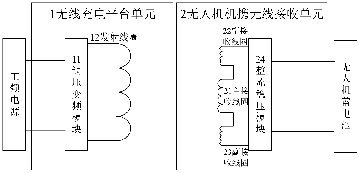
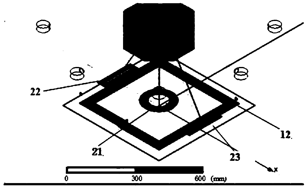
[0037] Such as figure 1 with figure 2 As shown, an anti-offset coupling coil for wireless charging of drones in this embodiment includes a drone wireless charging platform unit 1 and a drone carrying wireless receiving unit 2.
[0038] The UAV wireless charging platform unit 1 includes a voltage regulating and frequency conversion module 11 and a transmitting coil 12.
[0039] The unmanned aerial vehicle carrying wireless receiving unit 2 includes a main receiving coil 21 connected in series, two auxiliary receiving coils 22 and 23 and a rectifying and stabilizing module 24.
[0040] The unmanned aerial vehicle wireless charging platform unit 1 and the unmanned aerial vehicle carrying wireless receiving unit 2 transmit electric energy through resonance magnetic coupling. The voltage regulating and frequency conversion module 11 is connected to the transmitting coil 12, and the three receiving coils 21, 22, 23 are connected in series, and then connected to the rectifying and stabiliz...
Embodiment 2
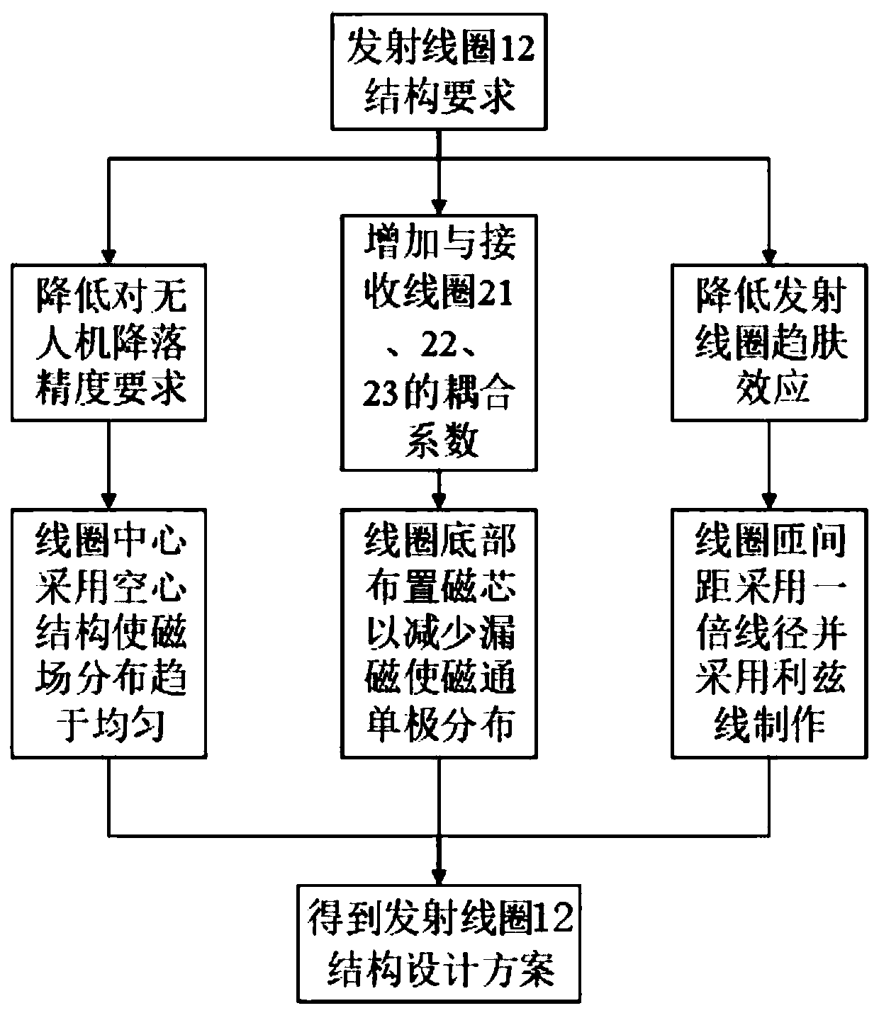
[0052] A method for designing an anti-offset coupling coil for wireless charging of drones includes the design of a transmitting coil and a receiving coil.
[0053] The transmitting coil design method includes:
[0054] (1) The center of the transmitting coil adopts a hollow structure to make the magnetic field distribution tend to be uniform, so as to reduce the lower requirements for the UAV;
[0055] (2) The magnetic core structure is arranged at the bottom of the transmitting coil to increase the coupling coefficient of the transmitting coil to the receiving coil;
[0056] (3) Regarding the winding method of the transmitting coil, the coil turn pitch is doubled wire diameter and made of litz wire to reduce the skin effect of the transmitting coil.
[0057] The receiving coil design method includes:
[0058] (1) Adopt the planar spiral coil structure as the energy receiving coil to increase the coupling coefficient of the receiving coil to the transmitting coil;
[0059] (2) The main r...
PUM
 Abstract
Description
Claims
Application Information
 - R&D
- Intellectual Property
- Life Sciences
- Materials
- Tech Scout
- Unparalleled Data Quality
- Higher Quality Content
- 60% Fewer Hallucinations
Browse by: Latest US Patents, China's latest patents, Technical Efficacy Thesaurus, Application Domain, Technology Topic, Popular Technical Reports.
© 2025 PatSnap. All rights reserved.Legal|Privacy policy|Modern Slavery Act Transparency Statement|Sitemap|About US| Contact US: help@patsnap.com


