Planar-type wireless power-receiving circuit module

a power-receiving circuit and wireless technology, applied in the direction of transformer/inductance magnetic cores, inductances, circuit arrangements, etc., can solve the problems of electromagnetic interference with electronic components or circuitry, weak magnetic field coupling between the loop antenna for power reception and the external loop antenna for power transmission, and unwanted magnetic field coupling between the external and internal, etc., to achieve enhanced magnetic flux passing, high density, and electromagnetic interference

Active Publication Date: 2022-01-04
MURATA MFG CO LTD
View PDF7 Cites 0 Cited by
  • Summary
  • Abstract
  • Description
  • Claims
  • Application Information

AI Technical Summary

Benefits of technology

[0006]Accordingly, the present disclosure provides a planar-type wireless power-receiving circuit module powered by a wireless power supply system with improved power efficiency and capable of suppressing electromagnetic interference that can adversely affect electronic components or circuitry.
[0009]The present disclosure offers an advantage in that strong magnetic field coupling occurs between the power-receiving coil and a power-transmitting coil. Furthermore, electromagnetic interference caused by external magnetic fields and affecting the electronic components and the electronic circuitry of the power-receiving circuit module may be suppressed. This eliminates or minimizes the possibility that the electronic components or the electronic circuitry will malfunction. The power-receiving coil is disposed in a cavity of the substrate having the electronic circuitry formed therein. This makes it possible to provide a low-profile, planar-type wireless power-receiving circuit module. A small and thin wireless power supply system with improved power efficiency is provided accordingly.

Problems solved by technology

The reason is that the magnetic field coupling between the loop antenna for reception of power and an external loop antenna for transmission of power is not strong.
Furthermore, unwanted magnetic field coupling can occur between the external loop antenna for transmission of power and an integrated circuit (IC) or any other electronic component incorporated in the smart card with biometric authentication.
The unwanted magnetic field coupling can cause electromagnetic interference with electronic components or circuitry.

Method used


Image

  • Planar-type wireless power-receiving circuit module
  • Planar-type wireless power-receiving circuit module
  • Planar-type wireless power-receiving circuit module

Examples


first embodiment

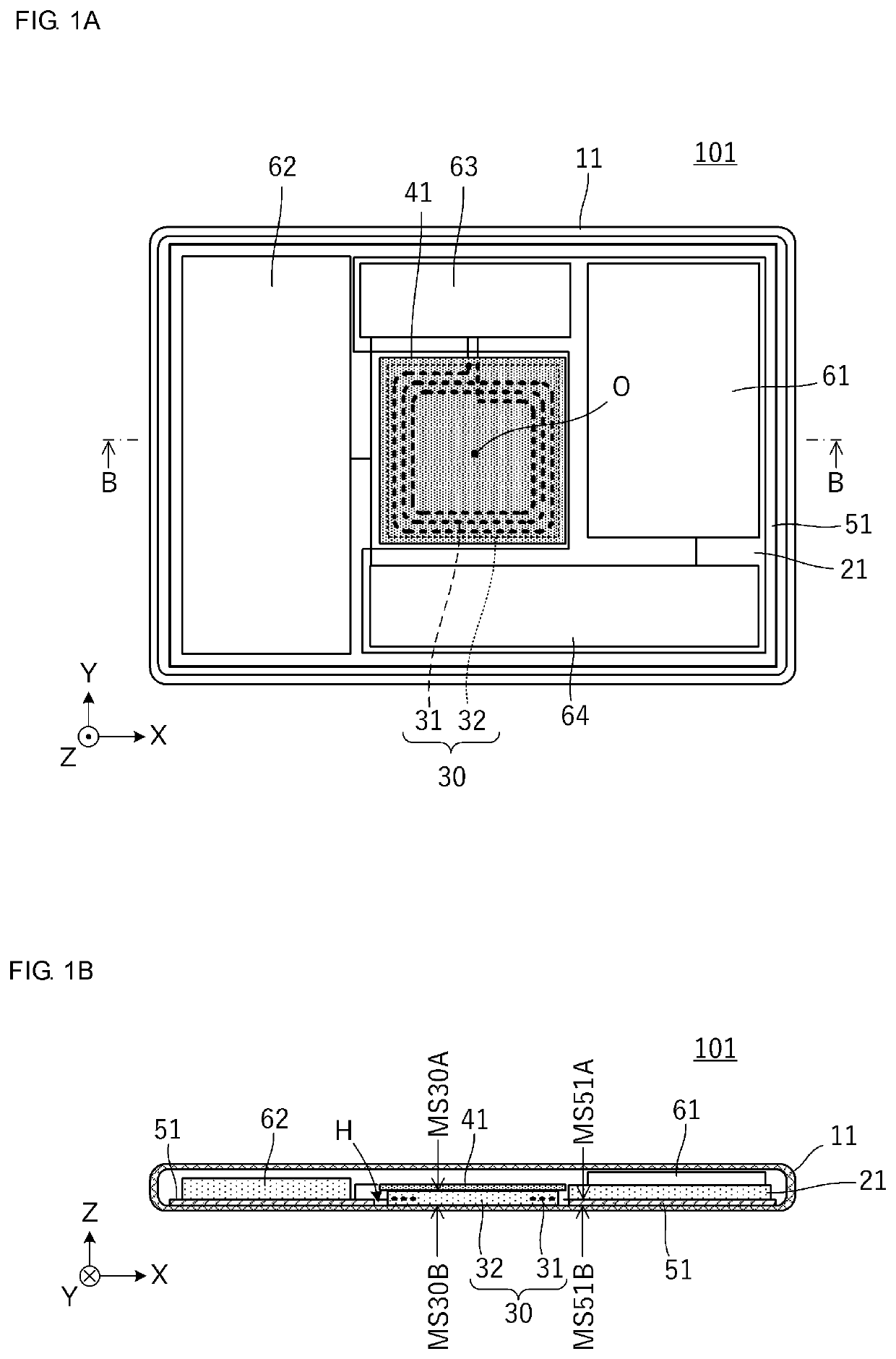
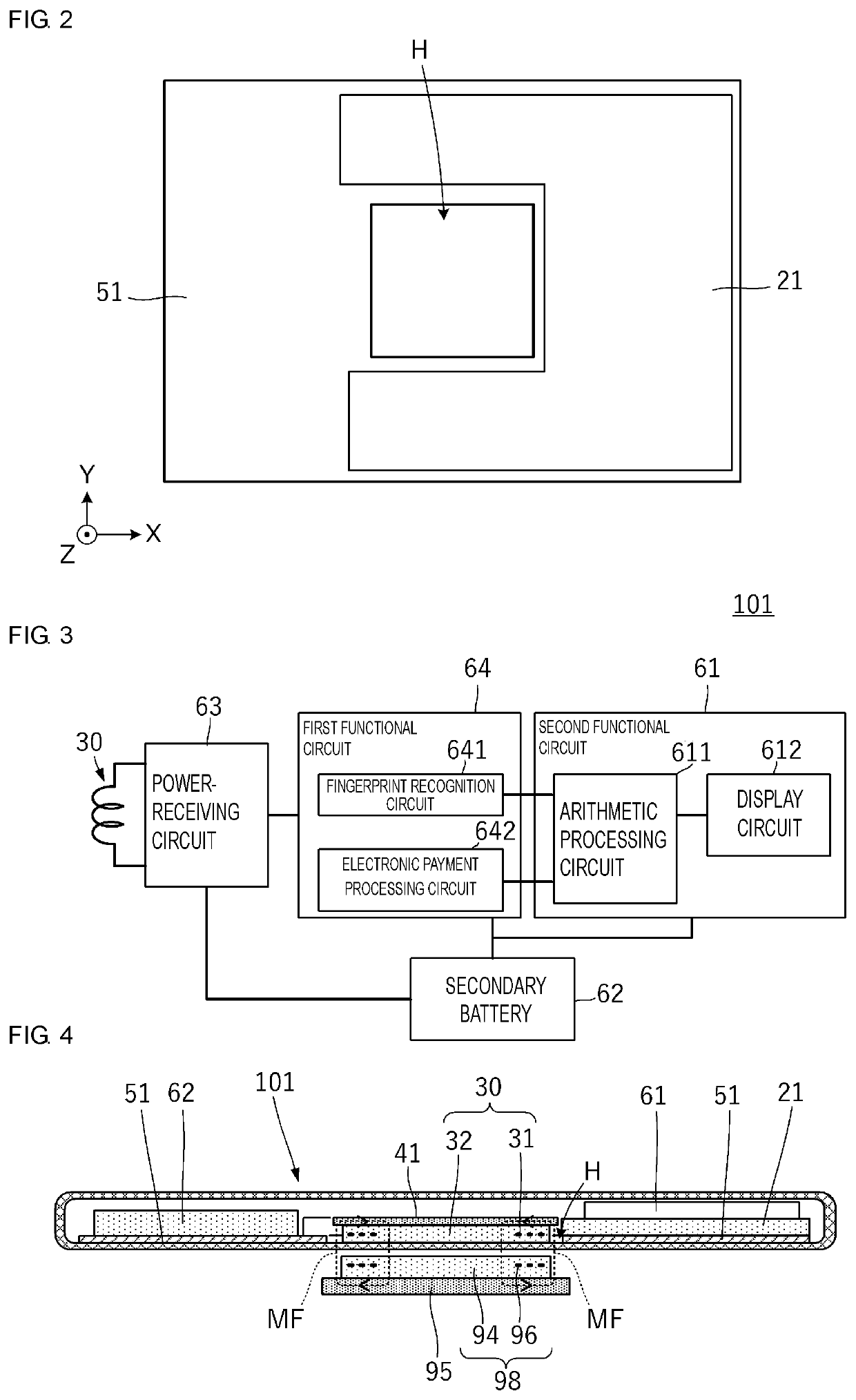
[0020]FIG. 1A is a plan view of a planar-type wireless power-receiving circuit module 101 according to a first embodiment, with an upper portion of a housing of the module being omitted. FIG. 1B is a sectional view of the planar-type wireless power-receiving circuit module 101 taken along line B-B in FIG. 1A. FIG. 2 is a plan view of a planar ground conductor 51 and a substrate 21.

[0021]The planar-type wireless power-receiving circuit module 101 includes the planar ground conductor 51 and the substrate 21 (see FIG. 2). The planar ground conductor has, in the middle section thereof, a cavity H, which has a square shape. The substrate 21 is disposed on a first main surface MS51A of the planar ground conductor 51. The substrate 21 is a multilayer substrate including dielectric layers stacked on top of each other in a manner so as to form electronic circuitry. The substrate 21 is a rigid substrate including an insulating base that is inflexible. The planar-type wireless power-receiving ...

second embodiment

[0041]The following describes a second embodiment, or more specifically, a planar-type wireless power-receiving circuit module in the form of a card for installation in a wireless power-transmitting device.

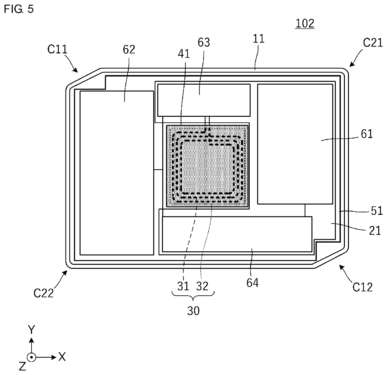
[0042]FIG. 5 is a plan view of a planar-type wireless power-receiving circuit module 102, with an upper portion of a housing of the module being omitted. The main difference between the planar-type wireless power-receiving circuit module 101 in FIG. 1A and the planar-type wireless power-receiving circuit module 102 is in the shape of the housing 11. When viewed in plan, the housing 11 of the planar-type wireless power-receiving circuit module 102 according to the present embodiment is substantially rectangular and has four corner sections, which are denoted by C11, C12, C21, and C22, respectively. The corner sections C11 and C12 are herein referred to as a first pair of diagonally opposite corners, and the corner sections C21 and C22 are herein referred to as a second pair of diag...

third embodiment

[0054]The following describe a third embodiment, or more specifically, a planar-type wireless power-receiving circuit module including a power-receiving coil whose configuration is different from the configurations described in the first and second embodiments.

[0055]FIG. 8A is a longitudinal sectional view of a planar-type wireless power-receiving circuit module 103A according to the third embodiment. As is clear from comparison with the example illustrated in FIG. 1B, the magnetic sheet 41 covers not only an upper face but also four lateral faces of the power-receiving coil substrate 32. Specifically, the magnetic sheet 41 covers five outer faces of the power-receiving coil substrate 32 that are not in contact with an inner bottom face of the housing 11. The magnetic sheet on the four lateral faces is part of the magnetic path passing through a region on the outside of the coil opening of the power-receiving coil conductor 31. This structure enables the magnetic sheet 41 to serve m...


PUM

PropertyMeasurementUnit
magnetic fluxaaaaaaaaaa
conductiveaaaaaaaaaa
flexibleaaaaaaaaaa

Abstract

A planar-type wireless power-receiving circuit module includes a planar ground conductor, a substrate, a power-receiving coil, and a magnetic sheet. The planar ground conductor has a cavity in the middle section thereof. The substrate is disposed on a first main surface of the planar ground conductor. The substrate includes dielectric layers stacked on top of each other in a manner so as to form electronic circuitry. The power-receiving coil is electrically connected to the electronic circuitry and is disposed in the cavity. The magnetic sheet overlaps the power-receiving coil when the planar ground conductor is viewed in plan. The magnetic sheet is part of a path of magnetic flux passing through the power-receiving coil and is disposed on a first main surface of the power-receiving coil.

Description

CROSS-REFERENCE TO RELATED APPLICATIONS[0001]This application claims benefit of priority to International Patent Application No. PCT / JP2019 / 015722, filed Apr. 11, 2019, and to Japanese Patent Application No. 2018-178810, filed Sep. 25, 2018, the entire contents of each are incorporated herein by reference.BACKGROUNDTechnical Field[0002]The present disclosure relates to a planar-type wireless power-receiving circuit module including predetermined electronic circuitry and configured to receive power wirelessly from the outside.Background Art[0003]A smart card configured to receive power wirelessly from the outside is disclosed in, for example, Japanese Unexamined Patent Application Publication No. 2012-221264, which describes a smart card with biometric authentication. The smart card includes, in addition to an IC chip for biometric authentication, a loop antenna for reception of power and a secondary battery. The smart card with biometric authentication is supplied with power stored ...

Claims


Application Information

Patent Timeline
Patent Type & Authority Patents(United States)
IPC IPC(8): H02J50/70H02J50/10H02J50/00H01F27/02H01F27/36H01F38/14H02J50/90H01F27/24
CPCH02J50/70H01F27/02H01F27/36H01F38/14H02J50/005H02J50/10H02J50/90H01F27/24H01L23/12H01L23/00H01F27/366H04B5/0037H04B5/0081
Inventor KAIWA, KOYOHOSOTANI, TATSUYA
Owner MURATA MFG CO LTD
Why Eureka
Try Eureka