
Twin brush with bearing plate

A brush device and electric power technology, applied in the direction of circuits, current collectors, electrical components, etc., can solve the problems of limited amplitude, separation of sheet parts, etc., and achieve the effect of high-quality contact

Active Publication Date: 2017-08-01
MERSEN FRANCE AMIENS
View PDF8 Cites 0 Cited by
  • Summary
  • Abstract
  • Description
  • Claims
  • Application Information

AI Technical Summary

Problems solved by technology

However, especially if the environment tolerates relatively strong vibrations, there is a risk of detaching the sheet
In addition, the amplitude of permitted motion will remain relatively limited

Method used


Image

  • Twin brush with bearing plate
  • Twin brush with bearing plate
  • Twin brush with bearing plate

Examples


Embodiment Construction

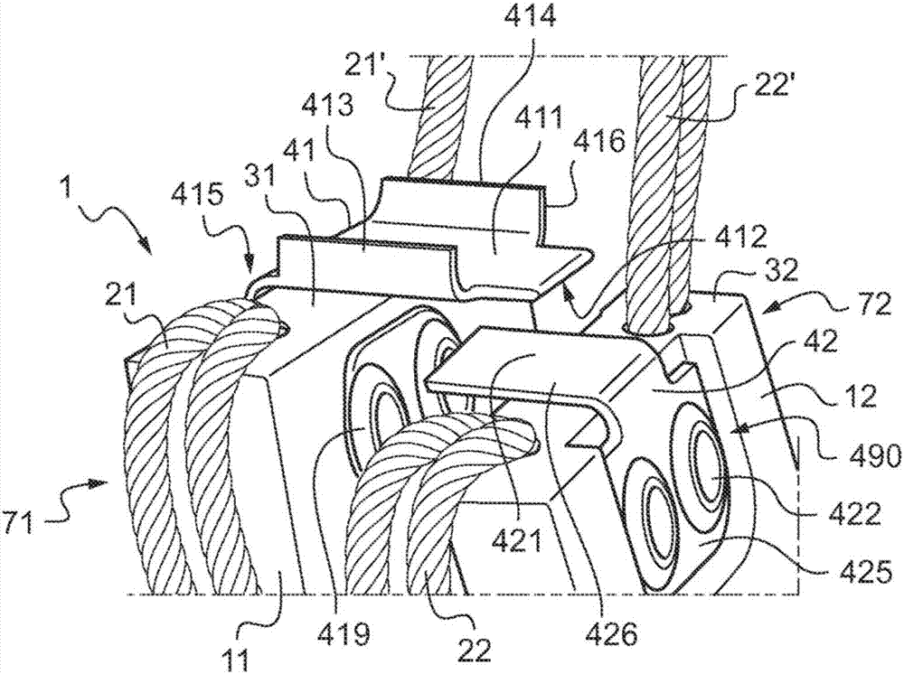
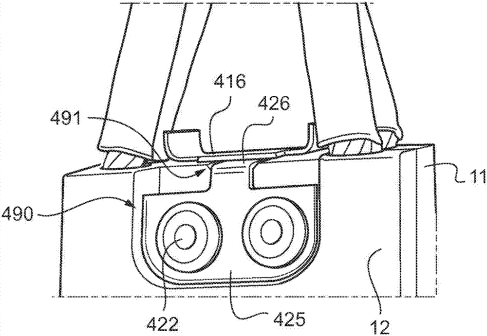
[0064] The illustrated brush arrangement is designed as a brush starter-generator for aviation applications.

[0065] Consequently, these brush arrangements, also called brushes, are subject to relatively high vibrations and, since the motor can be integral or enclosed, relatively high temperatures. These vibrations can easily cause other items to damage the motor. For example, there is a risk of detaching the brushes.

[0066] Advantageously, it can be considered to limit this risk by riveting the cable to the sheet.

[0067] There is also a risk of damaging the cable, or even the insulating sheath.

[0068] In addition, the front faces of the brushes, or sometimes even the side faces of the brushes, may wear due to friction of the brushes in the brush holder.

[0069] Finally, the contact surfaces of the brushes and the edges of the brushes are susceptible to relatively high electrical wear due to arcing caused by the brushes jumping on the commutator, especially when the...


PUM


Abstract

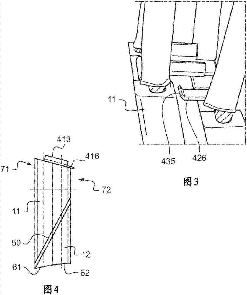
A brush device (1) comprising: a first (11) and a second (12) flange disposed side by side, each flange extending radially between a rubbing face intended to rub against a moveable element and a flange head (71, 72) intended to be connected electrically to another moveable element, a first plate (41) rigidly fixed to the first flange only and extending tangentially above the head of the second flange, in such a way as to transmit, when this first plate is loaded by pressure means, pressure forces on the second flange, a second plate (42), distinct from the first plate, rigidly fixed to the second flange only and extending tangentially above the head of the first flange in such a way as to bear on said first flange in the event of relative motion of the second flange with respect to the first flange towards the first moveable element.

Description

technical field [0001] The invention relates to the field of brushes for providing electrical contact between stationary parts / elements and rotating parts / elements in rotating electric machines. The rotating part may for example be a commutator part of an electric motor or a slip ring of a synchronous or asynchronous motor. [0002] More precisely, the invention relates to brushes for electric machines, and more particularly to split brushes. Background technique [0003] It is known to assemble several blades, usually graphite based, side by side to limit sparking and vibration effects, especially when the element used to slide relative to the brushes comprises a plurality of commutator bars, each blade having an associated potential and tolerate defects in misalignment of the strips with respect to each other. Therefore, providing several blades can thus achieve a better contact even in the case of surface defects. [0004] Thus, a split-lobe brush comprises two blades ...

Claims


Application Information

Patent Timeline
IPC IPC(8): H01R39/38
CPCH01R39/381H01R2201/26H01R39/20H01R39/26
Inventor 帕斯卡尔·拉尔蒂克劳伦特·洛谢
Owner MERSEN FRANCE AMIENS
Learn More