
Fertilizing system

A water supply system and fertilizer supply technology, which is applied in the direction of fertilization device, liquid fertilizer distribution, liquid fertilizer pressurized spreading method, etc., can solve the problems of difficult to control the concentration of added fertilizer, insufficient solubility, waste of water, etc.

Pending Publication Date: 2017-08-04
新疆慧尔智联技术有限公司
View PDF12 Cites 2 Cited by
  • Summary
  • Abstract
  • Description
  • Claims
  • Application Information

AI Technical Summary

Problems solved by technology

[0007] 2. The quantitative fertilizer supply system has small investment, simple operation, difficult automatic control, and cannot realize precise fertilization. It is suitable for soil with strong fertilizer retention capacity
[0011] Current irrigation problems: At present, domestic drip irrigation technology mainly uses manual drip irrigation. The irrigation time depends on experience, ranging from 6 hours to 48 hours, which can easily cause excessive irrigation. According to research, drip irrigation generally guarantees a soil depth of 30 ~40cm wet
Excessive irrigation not only leads to waste of water, but more seriously, it will lose the effective nutrients and fertilizer nutrients in the soil. At present, the fertilization method commonly used in drip irrigation is the fertilizer tank method. According to the difference in the pressure difference between the two ends of the fertilizer tank, through The flow of water carries the fertilizer into the irrigation system
However, this equipment is not easy to control the concentration of added fertilizer, nor can it achieve automatic management, and it is impossible to finely manage the amount of fertilizer added
At the same time, most of the fertilizers added are solid elemental fertilizers. The existing problems are that the solubility is not enough, the dripper is prone to clogging, the operation is inconvenient, and the cost is relatively high.

Method used


Image

  • Fertilizing system

Examples


Embodiment Construction

[0045] Features and exemplary embodiments of various aspects of the invention will be described in detail below. In the following detailed description, numerous specific details are set forth in order to provide a thorough understanding of the present invention. It will be apparent, however, to one skilled in the art that the present invention may be practiced without some of these specific details. The following description of the embodiments is only to provide a better understanding of the present invention by showing examples of the present invention. The present invention is by no means limited to any specific configurations and algorithms presented below, but covers any modification, substitution and improvement of elements, components and algorithms without departing from the spirit of the invention. In the drawings and the following description, well-known structures and techniques have not been shown in order to avoid unnecessarily obscuring the present invention.

...


PUM


Abstract

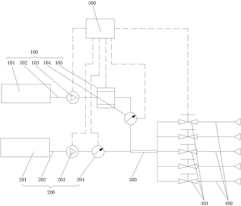
The invention provides a fertilizing system. The fertilizing system comprises: a water supply system used for supplying water; a fertilizer supply system used for supplying a liquid fertilizer; an irrigation main pipeline used for being connected with the water supply system and the fertilizer supply system to make the water supplied by the water supply system and the liquid fertilizer supplied by the fertilizer supply system mixed in the irrigation main pipeline; a plurality of irrigation branch tubes, wherein every irrigation branch tube is connected to the irrigation main pipeline, and every irrigation branch tube is provided with a control valve; and a controller used for controlling the water supply system to supply water to the irrigation main pipeline, controlling the fertilizer supply system to supply the fertilizer to the irrigation main pipeline, and controlling the opening and closing of the control valves. The fertilizing system provided in the embodiment of the invention can effectively control the water supply and the fertilizer supply in the fertilizing system, and can monitor the working state of the whole fertilizing system by the controller in order to adjust the fertilizing system in real time.

Description

technical field [0001] The invention relates to the technical field of liquid fertilizers, in particular to a fertilization system. Background technique [0002] At present, the use of liquid fertilizer has been promoted to a certain extent, but the current concentrated liquid fertilizer irrigation technology has the following characteristics: [0003] According to different control methods, automatic irrigation and fertilization systems can be divided into two categories: one is proportional fertilizer supply, which is characterized by supplying fertilizer to irrigation water at a constant nutrient ratio, and the fertilizer supply rate is proportional to the drip irrigation rate. The amount of fertilizer is generally expressed by the nutrient concentration of irrigation water, such as Venturi injection method and fertilizer pump method. The other type is quantitative fertilization, also known as total control, which is characterized in that the nutrient concentration chang...

Claims


Application Information

Patent Timeline
IPC IPC(8): A01C23/04
CPCA01C23/042Y02P60/21
Inventor 李保强
Owner 新疆慧尔智联技术有限公司
Learn More