
Intelligent paint spraying robot

A technology of robots and walking chassis, which is applied in the direction of manipulators, injection devices, manufacturing tools, etc., and can solve problems such as the inability to realize intelligent self-working

Inactive Publication Date: 2017-08-04
吴俊
View PDF0 Cites 14 Cited by
  • Summary
  • Abstract
  • Description
  • Claims
  • Application Information

AI Technical Summary

Problems solved by technology

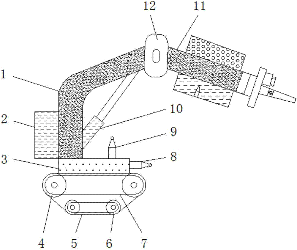
[0002] The painting robot is also called the spraying robot. It is an industrial robot that can automatically spray paint or spray other coatings. The painting robot is mainly composed of a robot body, a computer and a corresponding control system. The hydraulically driven painting robot also includes a hydraulic oil source, such as an oil pump and an oil tank. And motors, etc., mostly adopt 5 or 6 degrees of freedom joint structure, the arm has a large movement space, and can do complex trajectory movement, and its wrist generally has 2 to 3 degrees of freedom, which can move flexibly. More advanced The wrist of the painting robot adopts a flexible wrist, which can be bent in all directions and rotated. Its action is similar to that of a human wrist. It can easily penetrate into the interior of the workpiece through a small hole and spray its inner surface. The painting robot generally adopts hydraulic drive. , has the characteristics of fast action speed and good explosion-proof performance. It can be taught through hand-to-hand teaching or point display. Painting robots are widely used in automobiles, instruments, electrical appliances, enamel and other process production departments, but some painting robots now A large part still needs to rely on manual operation and cannot realize intelligent self-working. Therefore, people urgently need a new type of painting robot to work efficiently and intelligently.

Method used


Image

  • Intelligent paint spraying robot
  • Intelligent paint spraying robot
  • Intelligent paint spraying robot

Examples


Embodiment Construction

[0014] The following will clearly and completely describe the technical solutions in the embodiments of the present invention with reference to the accompanying drawings in the embodiments of the present invention. Obviously, the described embodiments are only some, not all, embodiments of the present invention. Based on the embodiments of the present invention, all other embodiments obtained by persons of ordinary skill in the art without making creative efforts belong to the protection scope of the present invention.

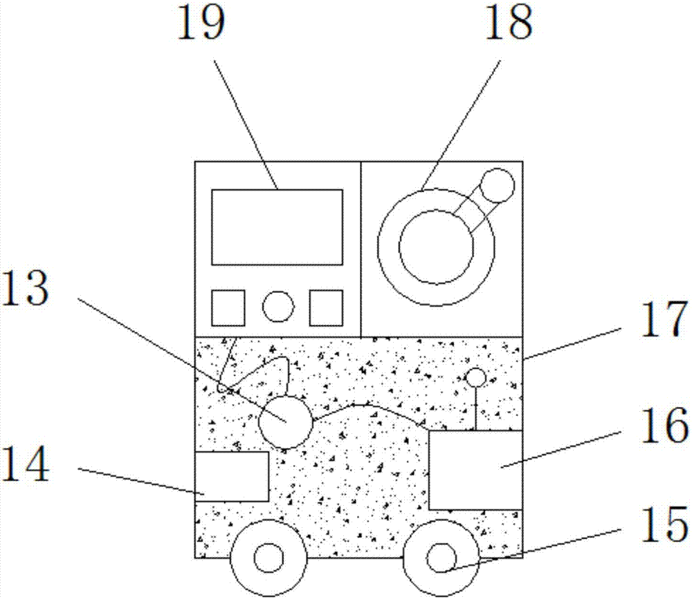
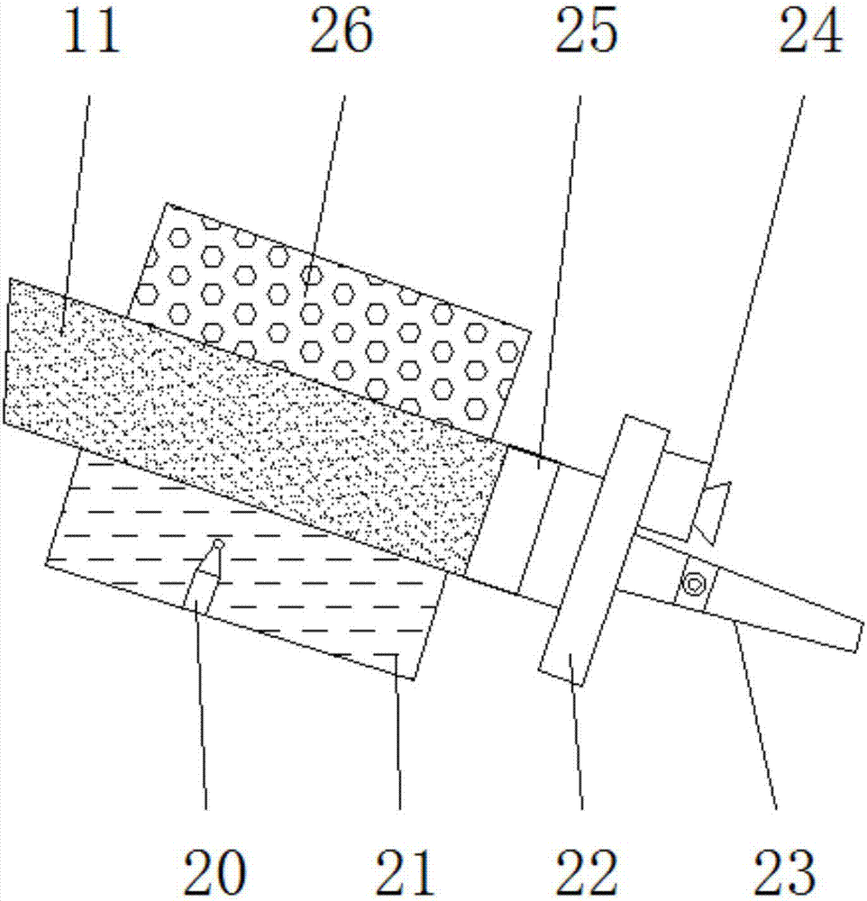
[0015] see Figure 1-3 , an embodiment provided by the present invention: an intelligent painting robot, comprising a walking chassis 5, a working arm 11 and a control box 17, the main crawler wheels 4 are installed inside the walking chassis 5 to achieve the purpose of moving and walking, the walking chassis 5 The upper end is equipped with a rotating base 3, which can rotate in all directions. The upper end of the rotating base 3 is equipped with a support a...


PUM


Abstract

The invention discloses an intelligent painting robot, which comprises a walking chassis, a working arm and a control box. The main crawler wheel is installed inside the walking chassis, and a rotating base is installed on the upper end of the walking chassis, and a support is installed on the upper end of the rotating base. One end of the support arm is equipped with a rotating shaft, the upper end of the rotating base is equipped with an infrared detection head, one end of the rotating base is equipped with an infrared emitting lamp, one end of the rotating shaft is equipped with a working arm, and the upper end of the working arm is installed There is an air pump, a paint box is installed at the lower end of the working arm, a pressure sensing probe is installed inside the paint box, a pressure sensing head is installed on the lower side of the air pump, and a QC200 data processor is installed at one end of the pressure sensing head , one end of the QC200 data processor is installed with an adjustable mist nozzle, and a control display is installed inside the control box. The intelligent painting robot of the invention has the characteristics of stable and efficient work, and improves the painting efficiency.

Description

technical field [0001] The invention relates to the technical field of robot equipment, in particular to an intelligent painting robot. Background technique [0002] The painting robot is also called the spraying robot. It is an industrial robot that can automatically spray paint or spray other coatings. The painting robot is mainly composed of a robot body, a computer and a corresponding control system. The hydraulically driven painting robot also includes a hydraulic oil source, such as an oil pump and an oil tank. And motors, etc., mostly adopt 5 or 6 degrees of freedom joint structure, the arm has a large movement space, and can do complex trajectory movement, and its wrist generally has 2 to 3 degrees of freedom, which can move flexibly. More advanced The wrist of the painting robot adopts a flexible wrist, which can be bent in all directions and rotated. Its action is similar to that of a human wrist. It can easily penetrate into the interior of the workpiece through a...

Claims


Application Information

Patent Timeline
Patent Type & Authority Applications(China)
IPC IPC(8): B05B13/04B25J5/00B25J11/00
CPCB05B13/0431B25J5/005B25J11/0075
Inventor 吴俊
Owner 吴俊
Learn More