Equipment for flocking production

A technology of flocking and equipment, which is applied to the device and coating of the surface coating liquid, which can solve the problems of easy damage, impact on work efficiency, and prone to wrinkles, etc., to reduce fabric wrinkles, ensure efficiency, and maintain beauty neat effect

Inactive Publication Date: 2017-08-04
JIASHAN SHENGLAISI CASHMERE
View PDF6 Cites 2 Cited by
  • Summary
  • Abstract
  • Description
  • Claims
  • Application Information

AI Technical Summary

Problems solved by technology

[0002] With the rapid development of social economy, the development of the garment industry is gradually flourishing. People's demand for fabrics also promotes the development and innovation of textile factories. The single operation structure of production machines is increasingly unable to meet the needs of modern production. Traditional production methods Sometimes it is not conducive to the improvement of production efficiency. When the factory is producing fabrics, it is often necessary to transport, dedust and flock the fabrics. If the design of the conveying device is not reasonable enough, if the fabric is too thick or too thin, it will be easier to be affected during transportation. If the fabric is damaged, the fabric may wrinkle, affecting the beauty of the fabric, and the work efficiency will also be affected; after the fabric is flocked, there may still be a large amount of lint remaining, which needs to be removed in time, otherwise it will not only affect the beauty of the fabric, but also affect the quality of the fabric. Its quality; the winding of the fabric is very important in the flocking production process. The common winding devices on the market have a single function, and the fabric is easy to be rolled and wrinkled. quality, so it is necessary to make some improvements to the common flocking equipment

Method used


Image

  • Equipment for flocking production

Examples


Embodiment Construction

[0018] In order to make the technical means, creative features, goals and effects achieved by the present invention easy to understand, the present invention will be further elaborated below in conjunction with illustrations and specific embodiments.

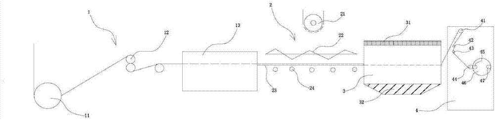
[0019] Such as figure 1 As shown, a kind of equipment for flocking production that the present invention proposes comprises stretching mechanism 1, and described equipment for flocking production also comprises flocking mechanism 2, dedusting mechanism 3 and winding mechanism 4, described One side of the stretching mechanism 1 is provided with a flocking mechanism 2, and one side of the flocking mechanism 2 is provided with a dust removal mechanism 3. The side is provided with a winding mechanism 4, and the flocking mechanism 2 and the winding mechanism 4 are respectively located on both sides of the dust removal mechanism 3; One side of the stretching roller 12 is provided with a stretching roller 12, and one side of the stret...


PUM


Abstract

The invention provides equipment for flocking production. The equipment comprises a stretching mechanism, a flocking mechanism, a dust removing mechanism and a rolling mechanism. The flocking mechanism is arranged on one side of the stretching mechanism. The dust removing mechanism is arranged on one side of the flocking mechanism. The rolling mechanism is arranged on one side of the dust removing mechanism. The stretching mechanism comprises a cloth feeding roller, a stretching roller and a stretching area. The flocking mechanism comprises a fluff adding device, a high-voltage electrode, a base material and a flapping rod, and the base material is located on one side of the stretching area. The dust removing mechanism is internally provided with a draught fan and a dust suction device. The rolling mechanism is internally provided with a tension roller, a flattening roller, a guiding roller, a pressing roller, a rolling roller, a rotary disc and an empty roll core. The dust removing mechanism is arranged in the equipment and internally provided with the draught fan and the dust suction device. A large amount of batting is possibly left on fabric obtained after flocking just now, when the fabric passes through the dust removing mechanism, the draught fan can blow the left batting up, the dust suction device sucks the batting in, and surface cleanliness and tidiness of the fabric are kept.

Description

technical field [0001] The invention relates to the field of flocking equipment, in particular to an equipment for flocking production. Background technique [0002] With the rapid development of social economy, the development of the garment industry is gradually flourishing. People's demand for fabrics also promotes the development and innovation of textile factories. The single operation structure of production machines is increasingly unable to meet the needs of modern production. Traditional production methods Sometimes it is not conducive to the improvement of production efficiency. When the factory is producing fabrics, it is often necessary to transport, dedust and flock the fabrics. If the design of the conveying device is not reasonable enough, if the fabric is too thick or too thin, it will be easier to be affected during transportation. If the fabric is damaged, the fabric may wrinkle, affecting the beauty of the fabric, and the work efficiency will also be affec...

Claims


Application Information

Patent Timeline
IPC IPC(8): B05C19/00B05C19/06B05C13/02
CPCB05C19/002B05C13/02B05C19/06
Inventor 李玉宇
Owner JIASHAN SHENGLAISI CASHMERE
Why Eureka
Try Eureka