Transmission device achieving tool up-and-down motion

A transmission device and tooling technology, which is applied in metal processing and other directions, and can solve problems such as occupying space

Pending Publication Date: 2017-08-04
YANGZHOU HENGJIA AUTOMATION EQUIP CO LTD
View PDF7 Cites 1 Cited by
  • Summary
  • Abstract
  • Description
  • Claims
  • Application Information

AI Technical Summary

Problems solved by technology

The device can realize automatic loading and unloading, which can improve production efficiency. However, this invention needs to install a vertical bar that moves up and down in the vertical direction to cooperate with the transmission mechanism to realize the up and down movement of the tooling. The space in the vertical direction cannot satisfy some places with height restrictions

Method used


Image

  • Transmission device achieving tool up-and-down motion
  • Transmission device achieving tool up-and-down motion
  • Transmission device achieving tool up-and-down motion

Examples


Embodiment Construction

[0022] Below in conjunction with accompanying drawing, the present invention is further described:

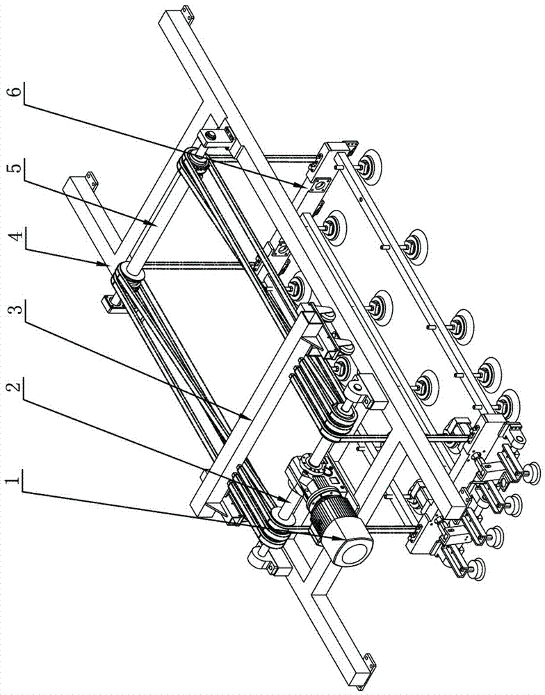
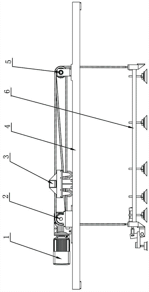
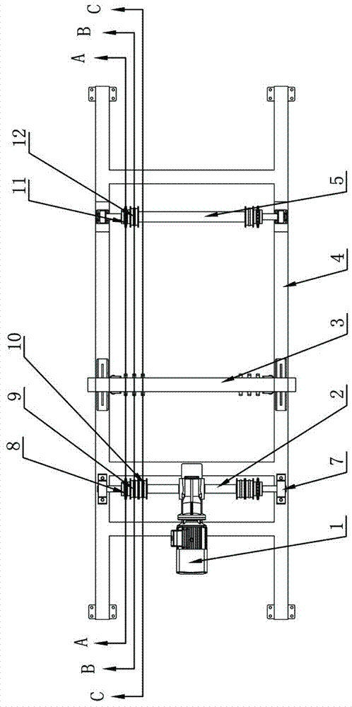
[0023] Such as Figure 1-8 The shown transmission device for realizing the up and down movement of the tooling includes a tooling 6 arranged under the frame 4, a transmission mechanism is installed on the frame 4, the transmission mechanism includes a motor 1, the motor 1 is installed and fixed on the frame 4, and the motor 1 is connected with a drive shaft 2, and the frame 4 is also provided with a driven shaft 5 parallel to the drive shaft 2. The drive shaft 2 and the driven shaft 5 are all installed on the frame 4 through the bearing seat 7. A pair of lifting components for controlling the lifting of the tooling 6 are installed on the driven shaft 5; Wheel one 8, reversing wheel one 9, reversing wheel two 10 and driven wheel one 11 and reversing wheel three 12 that are installed on the driven shaft 5; One 13, the two ends of the chain one 13 are connected to the both sides...


PUM


Abstract

The invention discloses a transmission device achieving tool up-and-down motion in the field of automatic feeding and discharging. The transmission device comprises a tool arranged below a rack. A transmission mechanism is mounted on the rack and comprises a motor. The motor is fixedly mounted on the rack and is in transmission connection with a driving shaft. A driven shaft parallel to the driving shaft is further arranged on the rack. The driving shaft and the driven shaft are mounted on the rack through bearing pedestals. A pair of lifting assemblies for controlling tool lifting is mounted on the driving shaft and the driven shaft. Tool up-and-down motion can be achieved, movement in the horizontal direction is converted into tool movement in the vertical direction, space in the vertical direction is saved, and the transmission device can be used for places with height restrictions in the vertical direction.

Description

technical field [0001] The invention relates to a processing machine tool, in particular to a loading and unloading device for a plate processing machine tool. Background technique [0002] The laser cutting automatic loading and unloading manipulator is disclosed in the Chinese patent database. Its announcement number is CN101628362A, and its publication date is: 2010-01-20. There is a support frame connected with the feeding mechanism of the machine tool, and the support frame is provided with a lifting mechanism that drives the suction cup frame to move up and down; the support frame is also provided with a deceleration motor, the middle part of the transmission shaft is connected with the deceleration motor, and the transmission shaft is installed on the On the support frame, there are gears at both ends of the transmission shaft, and the upper and lower sides of each gear mesh with a rack respectively. The outer ends of the two beams located on the lower side of the ge...

Claims


Application Information

Patent Timeline
IPC IPC(8): B23Q7/14
CPCB23Q7/1421
Inventor 严伟纪玉昕毛云雨
Owner YANGZHOU HENGJIA AUTOMATION EQUIP CO LTD
Why Eureka
Try Eureka