
Air valve air intake performance test device and test method

A technology of testing device and air valve, which is applied in the direction of measuring device, testing of mechanical parts, testing of machine/structural parts, etc. High cost and other problems, to achieve the effect of simple structure, less floor space and low cost

Active Publication Date: 2017-08-04
HEFEI GENERAL MACHINERY RES INST
View PDF7 Cites 7 Cited by
  • Summary
  • Abstract
  • Description
  • Claims
  • Application Information

AI Technical Summary

Problems solved by technology

Existing test devices for the air valve air intake test are all built on the principle of vacuum pumping, which is expensive and cannot fully fit the actual working conditions and cannot realize the measurement of large air intake conditions

Method used


Image

  • Air valve air intake performance test device and test method
  • Air valve air intake performance test device and test method
  • Air valve air intake performance test device and test method

Examples


Embodiment 1

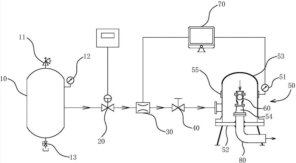
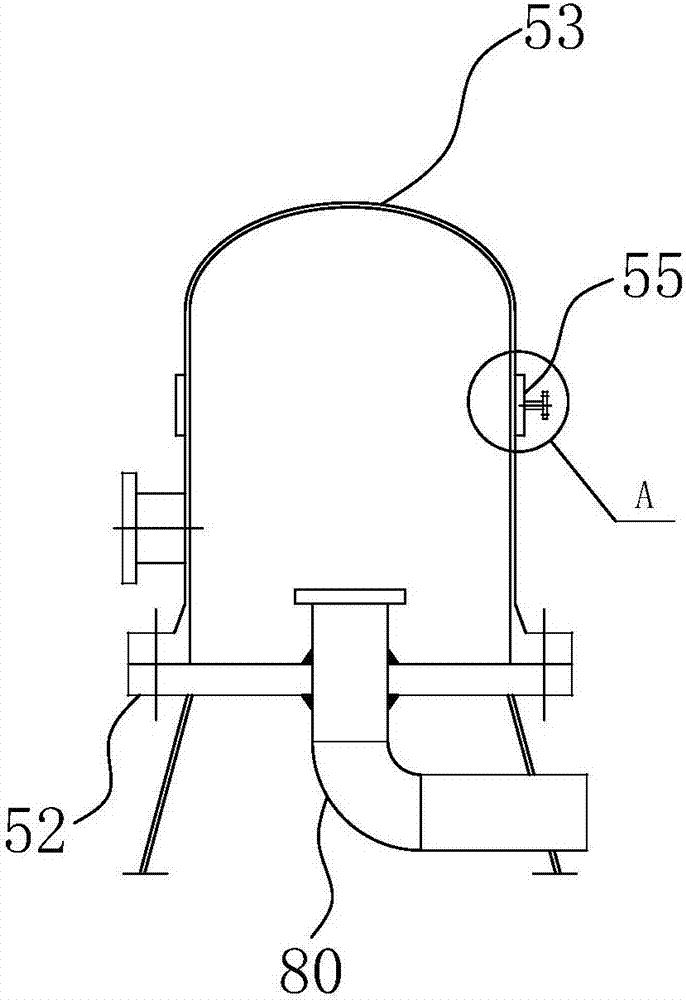
[0033] like figure 1 As shown: the air valve air intake performance testing device of the present invention includes a data acquisition unit 70 and an air storage tank 10, a flow regulating valve 20, a flow meter 30, and an air collecting device 50 installed sequentially on the test pipeline along the air flow direction , the air collecting device 50 is provided with a measured air valve 60 installed on the corresponding exhaust pipeline 80 , and a pressure gauge 1 51 for measuring the pressure inside the gas collecting device 50 is installed on the gas collecting device 50 . An on-off valve 40 is installed between the flow meter 30 and the gas collecting device 50 .

[0034] The traditional air valve intake performance test is often to use a vacuum pump to generate negative pressure in the installation pipeline of the air valve to be tested, so as to conduct the test process. However, the present invention realizes by increasing the pressure at the inlet end of the air valve...

Embodiment 2

[0042] The test method based on the air valve intake performance test device may further comprise the steps:

[0043] S1. Close the flow regulating valve 20 and the switch valve 40 located between the flow meter 30 and the gas collecting device 50, and fill the gas storage tank 10 with a sufficient amount of gas required for the test in advance;

[0044] S2. Adjust the opening of the switching valve 40 to the maximum, and then open the flow regulating valve 20. At this time, the medium flows out through the gas storage tank 10 into the test pipeline and then into the gas collection device 50, and then from small to large Gradually adjust the opening degree of the flow regulating valve 20, and at the same time, the data acquisition unit 70 acquires multiple sets of data measured by the flowmeter 30 and the pressure gauge 1 51;

[0045] During the test, when the data measured by the pressure gauge 1 reaches the pressure value of the set sampling point, keep the opening of the fl...


PUM


Abstract

The invention relates to an air valve air intake performance test device and a test method. The air valve air intake performance test device comprises a data acquisition unit, and an air storage tank, a flow control valve, a flow meter and an air collection device which are installed on a test pipe in sequence along the direction of air flow. The air collection device is internally provided with a tested air valve installed on a corresponding exhaust pipe. A pressure gauge I used for measuring the pressure inside the air collection device is installed on the air collection device. The air collection device can precisely simulate the air intake state of the air valve under actual working condition. Multiple groups of air intake pressure differences Delta P and corresponding air intake Q data can be obtained by gradually adjusting the flow control valve. The device and the method have the advantages of low cost, simple structure, and easy operation in the test process. The invention provides a simpler and novel way to test the air intake performance of an air valve.

Description

technical field [0001] The invention belongs to the technical field of air valve performance testing, and in particular relates to an air valve intake performance testing device and a testing method. Background technique [0002] The air valve is an important water hammer protection device in long-distance water supply projects. It can replenish air in time when there is negative pressure in the pipeline, eliminate the phenomenon of liquid column separation, and avoid accidents. The intake performance of the air valve is the main factor that must be considered when selecting the air valve. At this stage, the intake performance of the air valve is mainly measured by the test device. Existing test devices for air valve air intake testing are all built on the principle of vacuum pumping, which is expensive, cannot fully fit the actual working conditions, and cannot realize the measurement of large air intake working conditions. Therefore, those skilled in the art urgently need...

Claims


Application Information

Patent Timeline
Patent Type & Authority Applications(China)
IPC IPC(8): G01M13/00
CPCG01M13/00
Inventor 张继伟彭林王剑黄健范宜霖雷艳胡春艳
Owner HEFEI GENERAL MACHINERY RES INST
Learn More