
Friction vibration test device and test method thereof

A test device, friction and vibration technology, applied in the direction of measurement device, machine gear/transmission mechanism test, mechanical component test, etc., can solve problems such as difficulty in fault diagnosis of planetary gears

Inactive Publication Date: 2017-08-04
XIAN TECHNOLOGICAL UNIV
View PDF6 Cites 11 Cited by
  • Summary
  • Abstract
  • Description
  • Claims
  • Application Information

AI Technical Summary

Problems solved by technology

[0004] The purpose of the present invention is to provide a friction vibration test device and its test method, which are used to detect in real time the damage of key components such as the sun gear, planetary gear, and planet carrier of the gear reduction box during normal operation, and to solve the faults of the existing planetary gears Diagnosing Difficult Issues

Method used


Image

  • Friction vibration test device and test method thereof
  • Friction vibration test device and test method thereof
  • Friction vibration test device and test method thereof

Examples


Embodiment Construction

[0022] The present invention will be described in detail below in conjunction with the accompanying drawings and specific embodiments.

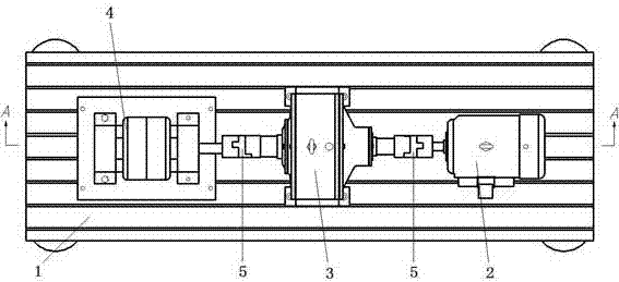
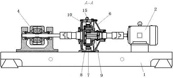
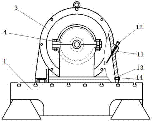
[0023] see Figure 1-Figure 6 The frictional vibration testing device includes a base 1, on the central axis of the upper end surface of the base 1, a motor 2, a gear reduction box to be tested 3 and a hydraulic dynamometer 4 are arranged in sequence; the output shaft of the motor 2 passes through a shaft coupling 5 is connected to the input shaft of the gear reducer 3 to be tested, and the output shaft of the gear reducer 3 to be tested is connected to the main shaft of the hydraulic dynamometer 4 through a coupling 5; the gear reducer 3 to be tested is fixedly provided with a piezoelectric acceleration sensor.

[0024] The gear reduction box 3 to be tested includes an outer casing 6, and an annular ring gear 7, a planetary carrier 8, a sun gear 9 and a plurality of planetary gears 10 are arranged in the outer casing 6; the described planet...


PUM


Abstract

The invention relates to a friction vibration test device and a test method thereof. The test device comprises a base. A motor, a to-be-tested gear reducer and a hydraulic dynamometer are arranged on the central axis of the upper end face of the base in sequence. The output shaft of the motor is connected with the input shaft of the to-be-tested gear reducer through a coupling. The output shaft of the to-be-tested gear reducer is connected with the spindle of the hydraulic dynamometer through a coupling. A piezoelectric acceleration sensor is fixedly arranged on the to-be-tested gear reducer. The test method combines friction test, wear test and vibration test. After multiple sets of information are fused, a new integrated state index is obtained, which is used as the basis of next step of state identification.

Description

technical field [0001] The invention belongs to the technical field of equipment detection in a mechanical transmission system, and in particular relates to a friction vibration testing device in a mechanical transmission and a testing method thereof. Background technique [0002] As a key transmission component in the national economy and national defense construction, planetary gears are widely used in mechanical transmission systems in wind power, aviation, shipbuilding, metallurgy, petrochemical, mining, lifting and transportation industries. The gearbox has many advantages such as light weight, small size, large transmission ratio, strong bearing capacity, and high transmission efficiency. However, in the harsh working environment of low speed and heavy load, the key components such as the sun gear, planetary gear, and planet carrier are often severely worn or damaged. Failures such as fatigue cracks. Based on the above situation, it is necessary to conduct friction, v...

Claims


Application Information

Patent Timeline
Patent Type & Authority Applications(China)
IPC IPC(8): G01M13/02
CPCG01M13/02G01M13/021G01M13/028
Inventor 曹蔚张洋王栋王宁王萌萌彭润玲杨科
Owner XIAN TECHNOLOGICAL UNIV
Learn More