Pipeline periscope

A technology of pipeline periscope and support rod, which is applied in the field of pipeline periscope, can solve the problems of time-consuming and physical strength, confusion of construction site, easy damage of cables, etc., and achieve the effect of improving on-site work efficiency, reducing labor intensity and being convenient to use.

Active Publication Date: 2017-08-04
BAODING JINDI SCI INSTR
View PDF6 Cites 3 Cited by
  • Summary
  • Abstract
  • Description
  • Claims
  • Application Information

AI Technical Summary

Problems solved by technology

[0002] At present, when the periscope takes pictures in the pipeline, it adopts the method of locking and clamping the support rod. The height of the center of the pipeline is unknown. After the first pre-adjustment of the height, the camera is put into the well, and the height is determined by observing the image. Then take the camera out of the well and adjust it again until the center of the camera is basically in the center of the pipeline before the video recording operation can be performed. This process may take several times
In addition, the depth of the inspection well ranges from 2 meters to more than ten meters, and the weight of the periscope ranges from 5 kg to 14 kg. Now the angle of the camera is manually adjusted, and it is extremely difficult to obtain a stable picture. The process of adjusting the support rod many times very time consuming and physical
Before starting the measurement of the pipeline periscope, a special cable needs to be used to connect the camera to the controller; after the pipeline periscope completes the measurement, the cable between the camera and the controller needs to be removed, the cable needs to be stored separately, the cable is easily damaged, and the cable length is limited The operation range of the operator is limited, the existence of the cable makes the construction site confusing, and the connection and removal of the cable takes time and physical strength

Method used


Image

  • Pipeline periscope
  • Pipeline periscope
  • Pipeline periscope

Examples


Embodiment Construction

[0024] The following will clearly and completely describe the technical solutions in the embodiments of the present invention with reference to the accompanying drawings in the embodiments of the present invention. Obviously, the described embodiments are only some, not all, embodiments of the present invention. Based on the embodiments of the present invention, all other embodiments obtained by persons of ordinary skill in the art without making creative efforts belong to the protection scope of the present invention.

[0025] In order to make the above objects, features and advantages of the present invention more comprehensible, the present invention will be further described in detail below in conjunction with the accompanying drawings and specific embodiments.

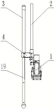
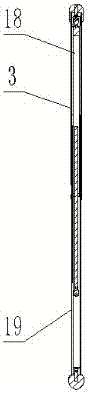
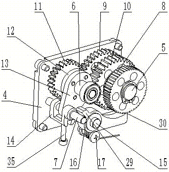
[0026] Such as Figure 1-5 As shown, the present invention provides a pipeline periscope, comprising a camera 1, a telescopic rod 2, a support rod 3 and a support rod connection block 4, the camera 1 is arranged a...


PUM


Abstract

The invention discloses a pipeline periscope. The pipeline periscope comprises a camera, an expansion link, a supporting rod and a supporting rod connecting block, wherein the camera is arranged at the lower end part of the camera; and the supporting rod and the expansion link are arranged on the supporting rod connecting block in parallel. The pipeline periscope is simple, is convenient to use, can be used for take stable pictures under a well without repeatedly taking equipment out of the well and adjusting the height and angle of the camera, and provides convenience to pipeline detection, so that the field working efficiency can be improved, and the labor intensity of detectors can be reduced.

Description

technical field [0001] The invention relates to the technical field of detection instruments, in particular to a pipeline periscope. Background technique [0002] At present, when the periscope takes pictures in the pipeline, it adopts the method of locking and clamping the support rod. The height of the center of the pipeline is unknown. After the first pre-adjustment of the height, the camera is put into the well, and the height is determined by observing the image. Then take the camera out of the well and adjust it again until the center of the camera is basically in the center of the pipeline before the video recording operation can be performed. This process may take several times. In addition, the depth of the inspection well ranges from 2 meters to more than ten meters, and the weight of the periscope ranges from 5 kg to 14 kg. At present, the angle of the camera is manually adjusted, and it is extremely difficult to obtain a stable picture. The process of adjusting t...

Claims


Application Information

Patent Timeline
Patent Type & Authority Applications(China)
IPC IPC(8): G02B23/24
CPCG02B23/2484
Inventor 王雪静杨韶辉徐凡王天
Owner BAODING JINDI SCI INSTR
Why Eureka
Try Eureka