Automatic wire binding device for straw baler

A straw bale and automatic technology, applied in agricultural machinery and implements, application, packaging, etc., can solve the time-consuming and labor-intensive problems of tying wires, and achieve the effect of improving efficiency and eliminating low work efficiency

Inactive Publication Date: 2017-08-08
曲阜鑫联重工机械制造有限公司
View PDF8 Cites 2 Cited by
  • Summary
  • Abstract
  • Description
  • Claims
  • Application Information

AI Technical Summary

Problems solved by technology

[0003] In order to overcome the time-consuming and labor-intensive problem of thread binding in the prior art, the present invention provides a mechanical device using a linkage mechanism to realize automatic thread binding and thread cutting of forage balls.

Method used


Image

  • Automatic wire binding device for straw baler
  • Automatic wire binding device for straw baler
  • Automatic wire binding device for straw baler

Examples


Embodiment Construction

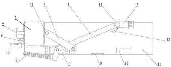
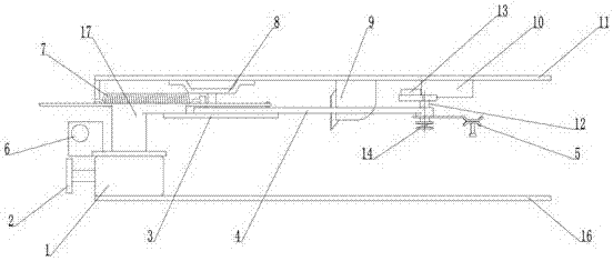
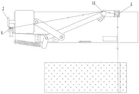
[0016] An automatic wire-tying device for a bale machine, matched with the bale machine, including a reducer fixed on a fixed plate and a wire-binding guide device, a cam is installed on the reducer, and the top of the cam is connected with the tail end of the connecting rod. The other end of the connecting rod is connected to the middle shaft of the support rod, and there is a movable shaft at the rear of the support rod connected to the fulcrum shaft on a fixed connection plate; the front end shaft of the support rod is connected to a crimping box; the cam rotates Drive the support rod to rotate along the fulcrum axis, thereby driving the crimping box to realize left and right reciprocating swing; a secant knife rest is provided at the position of the fixed plate corresponding to the full winding of the winding; the axial end of the crimping box is provided with a limit wheel, There are corresponding limit blocks on the fixed plate at the highest and lowest points of the move...


PUM


Abstract

The invention relates to an automatic wire binding machine for a straw baler. The automatic wire binding machine is matched with the straw baler and comprises a speed reducer fixed on a fixing plate and a bound wire unwinding device, wherein a cam is mounted on the speed reducer; the top of the cam is connected with a tail end shaft of a connecting rod; the other end of the connecting rod is connected with a middle shaft of a support rod; a fulcrum is also arranged on a rear part of the support rod; a movable shaft is connected with the fixing plate; a front end part shaft of the support rod is connected with a wire pressing box; the cam is rotated to drive the support rod to rotate about a fulcrum shaft, so as to drive the wire pressing box to swing to the left and right; a knife holder for cutting wires is arranged at a position at which the corresponding fixing plate is wound with the wires. The invention has beneficial effects of binding the wires automatically and effectively eliminating problems of low operating efficiency, overlong time and easy personal injury present when net ropes need to be cut off manually during traditional wire binding. The device is mounted on the straw baler to conveniently adjust wire binding time as needed, so as to improve efficiency.

Description

technical field [0001] The invention relates to silage processing equipment, in particular to an automatic thread-tying device on a silage bundling machine. Background technique [0002] The original bale tying machine is directly tied with a mesh nylon rope. After tying a bale, it is time-consuming and labor-intensive to manually cut the net rope, which is easy to cause personal injury. Contents of the invention [0003] In order to overcome the time-consuming and laborious problem of thread binding in the prior art, the present invention provides a mechanical device utilizing a link mechanism to realize automatic thread binding and thread cutting of forage balls. [0004] The technical scheme adopted by the present invention to solve the technical problem is: an automatic binding device for a bale machine, which is matched with the bale machine, and includes a speed reducer fixed on a fixed plate and a wire binding guide device. Cam, the top of the cam is connected to t...

Claims


Application Information

Patent Timeline
Patent Type & Authority Applications(China)
IPC IPC(8): A01F15/14
CPCA01F15/146
Inventor 孔令刚康海生张存
Owner 曲阜鑫联重工机械制造有限公司
Why Eureka
Try Eureka