Clamping hole tool of cutter and using method of clamping hole tool

A cutting machine and clamping technology, applied in the direction of sawing machine devices, manufacturing tools, metal sawing equipment, etc., can solve the problems of time-consuming and labor-intensive cutting accuracy, unsuitable for promotion and utilization, and uneven cutting surface of bar materials, etc., to ensure cutting Excellent quality, convenient operation of removing the saw blade, and simple structure

Inactive Publication Date: 2017-08-08
浙江阿波罗工具有限公司
View PDF6 Cites 16 Cited by
  • Summary
  • Abstract
  • Description
  • Claims
  • Application Information

AI Technical Summary

Problems solved by technology

[0002] At present, when producing automobile brake pads, it is necessary to cut steel bars into required lengths. However, most of the existing technologies use manual feeding and cutting, which is not only time-consuming and labor-intensive, but also has poor cutting accuracy, and also reduces production efficiency. However, the automatic feeding of the machine does not have a good fixture to ensure the stability of the bar during cutting, resulting in uneven cut surfaces of the bar during cutting, which is not suitable for widespread promotion and utilization.

Method used


Image

  • Clamping hole tool of cutter and using method of clamping hole tool
  • Clamping hole tool of cutter and using method of clamping hole tool
  • Clamping hole tool of cutter and using method of clamping hole tool

Examples


Embodiment Construction

[0025] The following will clearly and completely describe the technical solutions in the embodiments of the present invention with reference to the accompanying drawings in the embodiments of the present invention. Obviously, the described embodiments are only some, not all, embodiments of the present invention. The specific embodiments described here are only used to explain the present invention, not to limit the present invention. Based on the embodiments of the present invention, all other embodiments obtained by persons of ordinary skill in the art without making creative efforts belong to the protection scope of the present invention.

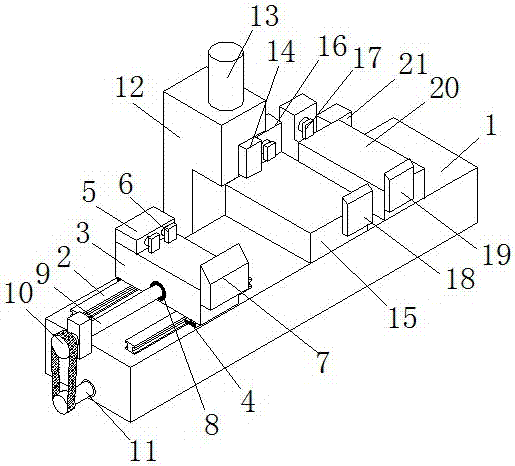
[0026] The present invention provides such Figure 1-4 The clamping mouth tooling of a cutting machine shown includes a base 1 and a feeding seat 3, a slide rail 2 is fixed on the left side of the top of the base 1, and the bottom of the feeding seat 3 is fixed on the slide rail through a slider 4 2 is slidingly connected with the slide ...


PUM


Abstract

The invention discloses a clamping hole tool of a cutter and a using method of the clamping hole tool. The clamping hole tool comprises a base and a feeding base, wherein a slide rail is fixedly arranged at the left side of the top of the base; the bottom of the feeding base is fixedly arranged on the slide rail through a slide block and is in sliding connection with the slide rail; a supporting frame is welded on the position, at the right side of the feeding base, at the rear end of the top of the base; a gas pump is fixedly mounted on the top of the supporting frame; a transmission shaft of the gas pump penetrates through the supporting frame and is fixedly connected with a telescopic pole; the bottom of the telescopic pole is fixedly connected with a limiting block; a pressure plate is fixedly arranged on the bottom of the limiting block; a cutting base is fixedly mounted at the right side of the top of the base; a material return base is fixedly arranged on a position, at the right end of the cutting base, at the right side of the base; and a regulating base is arranged at the right side of the rear end of the material return base. The clamping hole tool is simple and reasonable in structural design, is convenient to operate, saves time and labor, is safe and stable, ensures rod cutting quality and velocity, is wide in scope of application, and is beneficial for spreading and popularizing.

Description

technical field [0001] The invention belongs to the technical field of mechanical processing, and in particular relates to a clamping tool for a cutting machine. At the same time, it also relates to a method for using the tooling of the clamping mouth of the cutting machine. Background technique [0002] At present, when producing automobile brake pads, it is necessary to cut steel bars into required lengths. However, most of the existing technologies use manual feeding and cutting, which is not only time-consuming and labor-intensive, but also has poor cutting accuracy, and also reduces production efficiency. However, the machine automatic feeding does not have a good fixture to ensure the stability of the bar when cutting, thus causing the bar to have an uneven cut surface when cutting, which is not suitable for widespread promotion and utilization. Contents of the invention [0003] The purpose of the present invention is to solve the shortcomings in the prior art, and...

Claims


Application Information

Patent Timeline
Patent Type & Authority Applications(China)
IPC IPC(8): B23D47/04B23D59/02
CPCB23D47/04B23D59/02
Inventor 王楼峰王志伟麻锦春李彦修楼群英
Owner 浙江阿波罗工具有限公司
Why Eureka
Try Eureka