Flying shears with high speed and definite length

A fixed-length and flying shear technology, which is applied in the direction of shearing devices, shearing machine equipment, and devices for shearing forming blanks, can solve the problems of poor synchronization of cutting and feeding, waste of time, and high labor intensity, so as to improve synchronization accuracy and ensure Improvement of incision quality and work efficiency

Inactive Publication Date: 2007-09-12
大连立达工业设备有限公司
View PDF0 Cites 13 Cited by
  • Summary
  • Abstract
  • Description
  • Claims
  • Application Information

AI Technical Summary

Problems solved by technology

The wire cutting equipment with this structure is very troublesome when changing the cutting length of the wire. It must be stopped to replace the cam mechanism and the transmission device. The cutting length cannot be changed online, which wastes time, high labor intensity, increases production costs, and cuts into synchronization. Poor performance, easy to produce beveled edges and burrs at the incision

Method used


Image

  • Flying shears with high speed and definite length
  • Flying shears with high speed and definite length
  • Flying shears with high speed and definite length

Examples


Embodiment Construction

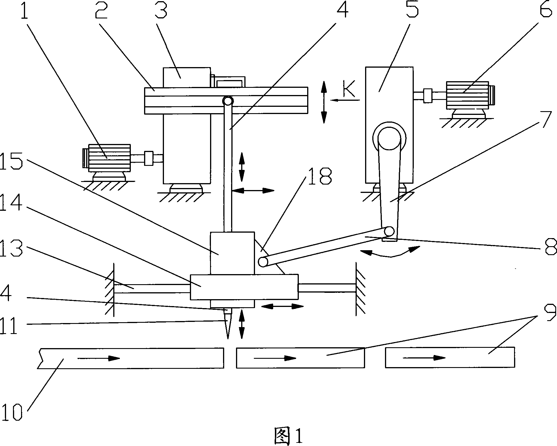
[0010] As shown in the figure: 5 is the first cam mechanism, the input shaft of the first cam mechanism 5 is connected with the motor 6 through a shaft coupling, and its output shaft is connected with one end key of the first rocker arm 7, and the first rocker arm 7 The other end is pivotally connected with one end of the swing rod 8 through a pin shaft, and the other end of the swing rod 8 is pivotally connected with the connecting plate 18 through a pin shaft. The connecting plate 18 is fixedly connected with the mobile car 14 and the cutter bar cover body 15. The mobile car 14 is provided with a guide sleeve and is set on the guide rod 13. The guide rod 13, the first cam mechanism 5, and the motor 6 are all fixedly connected with the frame. .

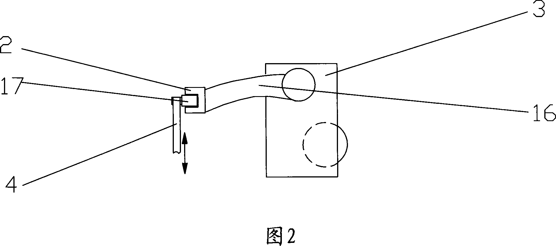
[0011] The input shaft of the second cam mechanism 3 is connected with the cutting motor 1 through a coupling, the output shaft of the second cam mechanism 3 is keyed to one end of the second rocker arm 16, and the other end of the s...


PUM


Abstract

The present invention relates to metal wire cutter, and is especially one kind of high speed fixed-length flying shears, which includes two motors, and two independent cam mechanisms. Each of these two cam mechanisms is connected to one of the motors and the shears through transmission mechanism. During cutting, these two motors may be controlled separately to change speeds and thus the cut length without need of stop. The present invention has high work efficiency, reduced labor strength, synchronous operations in two direction and high cut quality.

Description

technical field [0001] The invention relates to a metal wire cutting device, in particular to a high-speed fixed-length flying shear, which is mainly used for online fixed-length cutting of metal wires according to processing requirements, and the length of the wires can be changed at will through the control device during the operation. . Background technique [0002] The current equipment structure for continuous cutting of metal wires is: there are two cam mechanisms, wherein the input end of the first cam mechanism is connected to the motor, the motor is connected to the control device, and an output end of the first cam mechanism is connected to the first rocker arm. One end, the other end of the first rocker arm is connected to the shaft of one end of the swing rod, and the other end of the swing rod is connected to the moving axle. , the mobile vehicle can be driven to reciprocate along the guide rod by the first rocker arm and the swing rod. The other output end of...

Claims


Application Information

Patent Timeline
Patent Type & Authority Applications(China)
IPC IPC(8): B21F11/00B23D25/02B23D25/04
Inventor 雷鸣
Owner 大连立达工业设备有限公司
Why Eureka
Try Eureka