Vibrating table for cement component

A vibrating table and component technology, applied in the direction of ceramic molding machines, manufacturing tools, etc., can solve the problems of increasing the vibration effect of the vibration plate, increasing the vibration effect, reducing the vibration effect, etc., to reduce the mutual interference of dual-frequency vibration, increase the vibration effect and weaken it , to eliminate the effect of vibration offset

Pending Publication Date: 2017-08-08
高唐县鼎力建筑机械有限公司
View PDF6 Cites 2 Cited by
  • Summary
  • Abstract
  • Description
  • Claims
  • Application Information

AI Technical Summary

Problems solved by technology

[0003] In order to solve the problem of the poor vibration effect of the existing vibrating table, the present invention enables the vibrating plate to vibrate freely by arranging a spring under the vibrating plate, and the present invention provides a limiting protrusion for limiting the vibrating plate, and A limit card slot is set on the fixing seat below the plate, so that there is no hard fixed support or fixed limit device between the vibrating plate and the fixing seat, so that the vibrating plate can vibrate freely within a limited range, greatly increasing the The weakening of the vibration effect caused by the fixed connection between the traditional vibrating plate and the fixed seat; at the same time, the present invention independently installs the vibrating motor that drives the vibrator under the vibrating plate, that is to say, the vibrating motor is not installed on the fixed seat or vibrates board, thereby effectively reducing the mutual interference of dual-frequency vibrations caused by motor vibration and vibration plate vibration, thereby eliminating the vibration offset caused by motor vibration to vibration plate vibration, and increasing the vibration effect of the vibration plate; for those that cannot meet various models 1. The problem of the use of molds for cement components of different styles. The present invention provides a sliding locking mechanism on the top surface of the vibrating table, and the technical scheme of using the sliding locking mechanism can perform sliding locking on cement components of different shapes according to different needs. When adjusting and using, you only need to place the cement construction mold on the vibrating table and lock it, so as to meet different use requirements, and at the same time, it can effectively fix the vibrating cement components
[0004] The present invention also solves the problem of poor vibration effect in the prior art. In the prior art, the vibrating table is designed as a flat plate, and the vibrating table is installed on the body through elastic parts. This method has the following defects: because the vibrating table is flat One-piece design, therefore, there will be a power transmission between the connection points of the vibrating table and the body, especially the power transmission between adjacent connection points is more obvious. This kind of power transmission is essentially the consumption of vibration force. Thus, the vibration effect is reduced; in order to solve this technical problem, the present invention adopts the technical solution of the extension bracket. Due to the adoption of this technical solution, there is no bracket connection between the extension bracket and the connection point of the body, only through The bracket is connected to the vibrating table in the middle, and the vibrating table directly bears the cement component to be vibrated, so the vibration force is directly transmitted to the cement component to be vibrated, making full use of the vibration effect, increasing the compactness of the cement, and realizing high-frequency vibration

Method used


Image

  • Vibrating table for cement component
  • Vibrating table for cement component
  • Vibrating table for cement component

Examples


Embodiment Construction

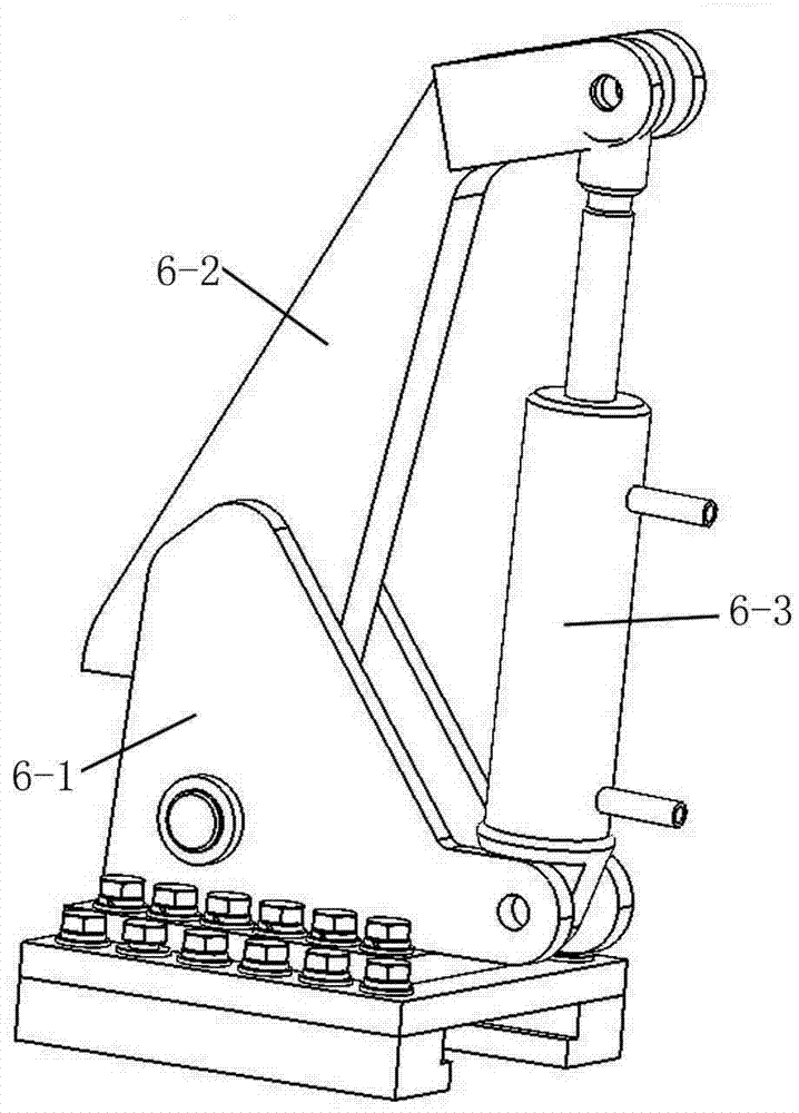
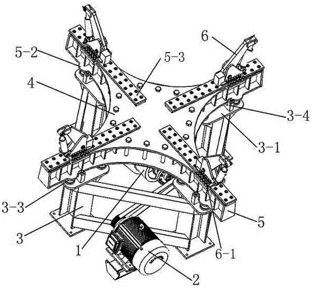
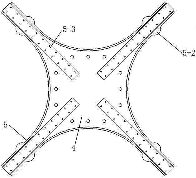
[0017] Such as Figure 1-5 As shown, a cement component vibration table includes 1 vibrator and 2 drive motors that drive the vibrator, and also includes 3 fixed seats and 4 vibration plates that are independent of each other. The top surface of the 4 vibration plates is used for placing non-fixed connection on The vibrating cement component on the vibrating plate, the 1 vibrator is fixedly mounted on the bottom surface of the 4 vibrating plate, the side ends of the 4 vibrating plate are provided with at least three groups of 5 extension brackets, and the bottom surface of the 5 extension brackets is provided with 5 -1 spring slot, the 5 extension bracket at the side end of the 5-1 spring slot is provided with a 5-2 limit convex seat; the 3 fixed seat below the 5-1 spring slot is equipped with a 3-1 bearing Plate, the 3-1 bearing plate is provided with a 3-2 spring card slot two corresponding to the 5-1 spring card slot, and the 5-1 spring card slot and the 3-2 spring card slot...


PUM


Abstract

The invention discloses a vibrating table for a cement component. The vibrating table comprises a vibrator and a drive motor for driving the vibrator as well as a fixed plate and a vibrating plate, which are mutually independent, wherein the vibrating plate is used for placing a to-be-vibrated cement component; the vibrator is arranged on the bottom surface of the vibrating plate; an extending bracket is arranged at the side end of the vibrating plate; a spring blocking slot is formed in the bottom surface of the extending bracket; the extending bracket at the side end of the spring blocking slot is equipped with a limiting convex base; a bearing plate is mounted on a fixed plate below the spring blocking slot; a spring blocking slot II which corresponds to the spring blocking slot is formed in the bearing plate; springs are inserted and connected in the spring blocking slot and the spring blocking slot II; a limiting blocking plate is mounted on the bearing plate at the side end of the spring blocking slot II; a limiting blocking slot is formed in the limiting blocking plate; and the limiting blocking slot is formed in the side end of a limiting convex base and is used for placing the extending bracket, so that the vibrating plate performs limited shaking or motion in the limiting blocking slot. The vibrating table effectively solves the problems that the vibrating table is not good in vibrating effect, and cannot meet use of various models, realizes high-frequency vibration and increases compactness of the cement component.

Description

Technical field [0001] The invention relates to a support type cement component vibration table. Background technique [0002] In the field of road or engineering construction, cement components are often used. Now cement components are mostly prepared by prefabricated molds and assembled during use. This method greatly improves installation efficiency. In order to increase the compactness of cement prefabricated construction, it is usually necessary Vibrate the cement construction. According to different usage needs, the cement construction takes a variety of styles, such as round, diamond, square, etc., which requires diversified cement construction molds corresponding to it. Because of the diversity of cement construction molds, In actual vibration, it is necessary to match different vibration tables. The prior art does not yet have a vibration table suitable for molds of various shapes. As a result, the vibration table needs to be purchased in multiple models, which increases...

Claims


Application Information

Patent Timeline
Patent Type & Authority Applications(China)
IPC IPC(8): B28B1/087
CPCB28B1/0873
Inventor 姚雯彬
Owner 高唐县鼎力建筑机械有限公司
Why Eureka
Try Eureka