Jet-flow control structure for overflow surface of high dam

A technology of jet control and overflow surface, which is applied in water conservancy projects, sea area engineering, coastline protection, etc., can solve the problems of strong downstream backflow, downstream riverbed deformation, serious problems, etc., and achieve stable water flow shape, slight riverbed scour, and sufficient energy dissipation Effect

Pending Publication Date: 2017-08-08
FUJIAN PROVINCIAL INVESTIGATION DESIGN & RES INST OF WATER CONSERVANCY & HYDROPOWER
View PDF5 Cites 7 Cited by
  • Summary
  • Abstract
  • Description
  • Claims
  • Application Information

AI Technical Summary

Problems solved by technology

[0004] 1. The scouring of the downstream riverbed is relatively serious, and when the scouring pit is too deep, it may endanger the safety of hydraulic structures;
[0005] 2. Strong backflow in the downstream can cause serious erosion of the bank slope;
[0006] 3. There are many deposits in the downstream of the scour pit, which may deform the downstream river bed, and the

Method used


Image

  • Jet-flow control structure for overflow surface of high dam
  • Jet-flow control structure for overflow surface of high dam
  • Jet-flow control structure for overflow surface of high dam

Examples


Embodiment 1

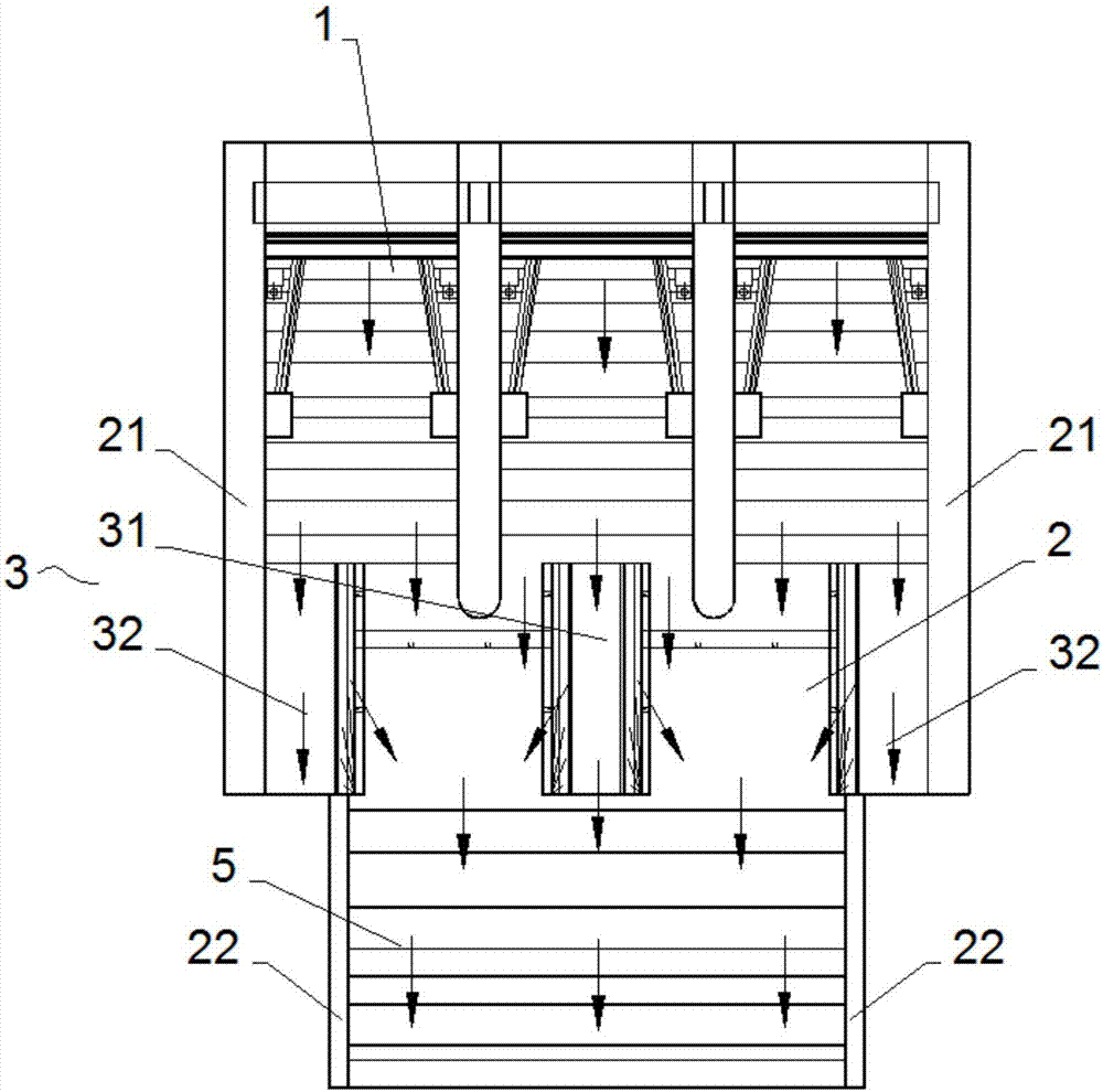
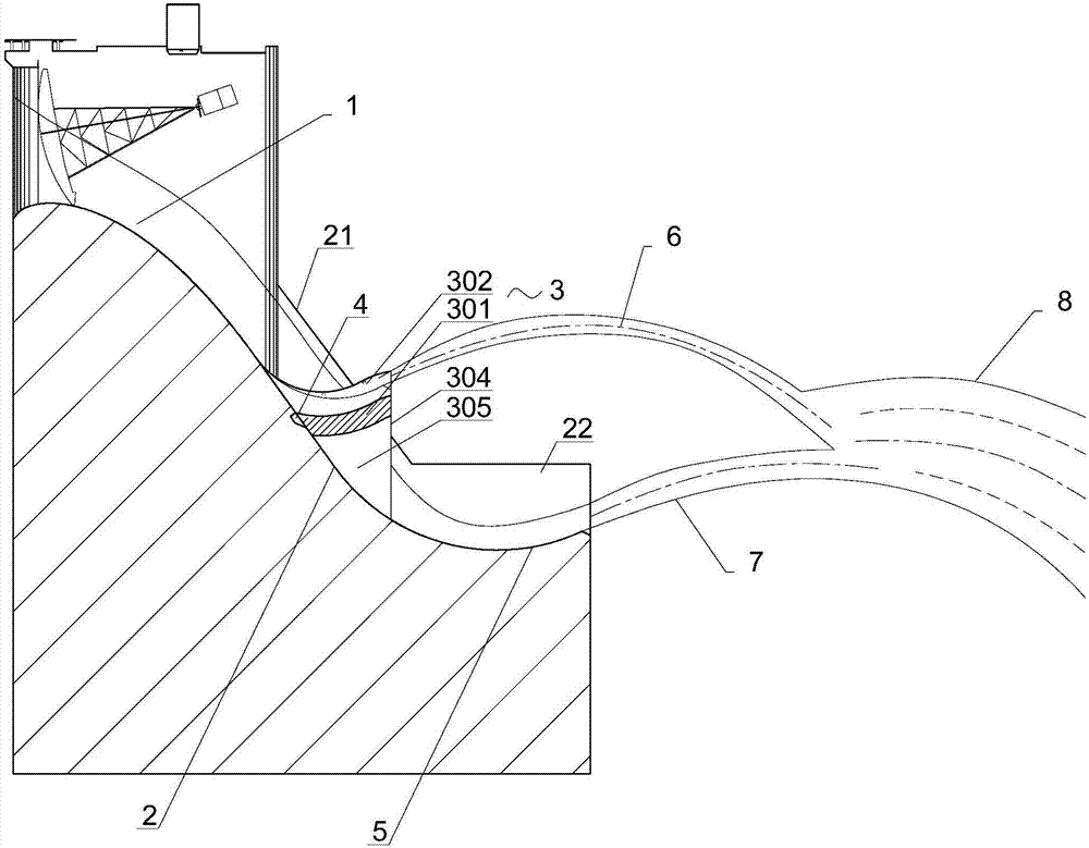
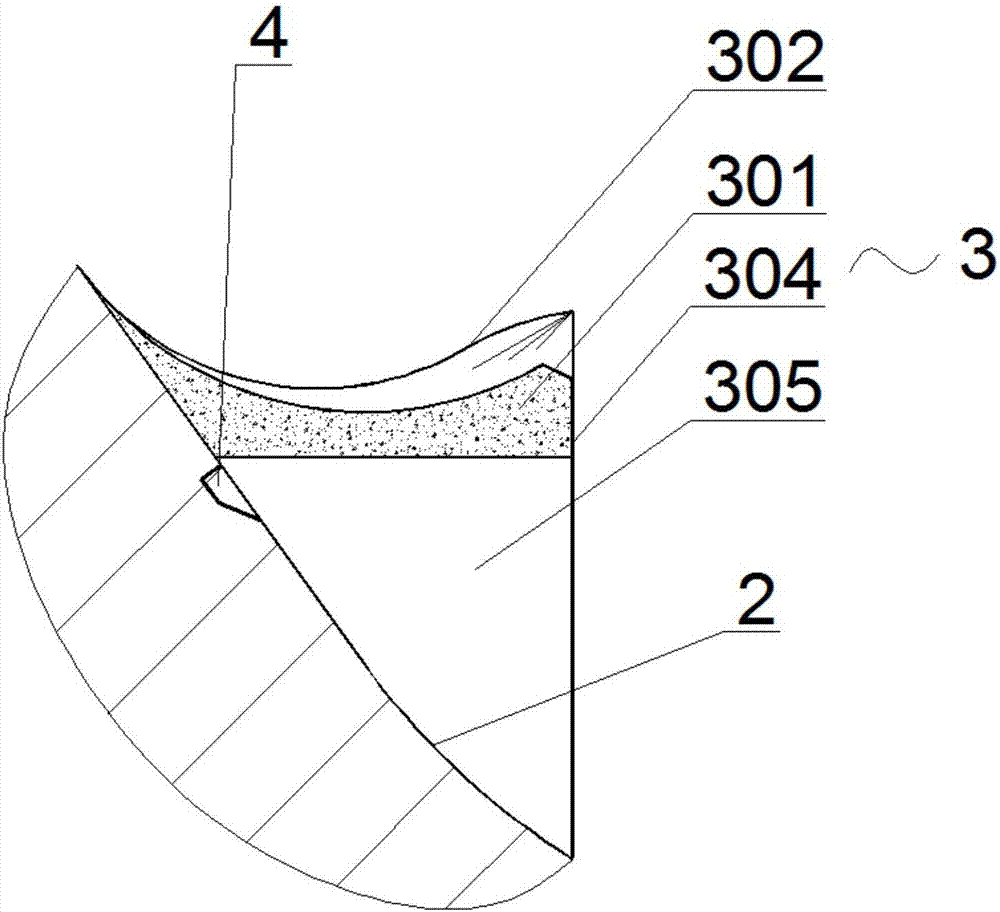
[0033] see Figure 1 to Figure 4 As shown, the high dam overflow surface jet flow control structure of the present invention includes an overflow gate hole 1 arranged on the dam body, and the end of the WES curve of the dam body weir surface below the overflow gate hole 1 joins the steep groove section 2, and the steep groove The end of the section 2 is provided with a continuous ridge 5, and the steep trough section 2 is provided with an overflow surface ridge 3 capable of partitioning the water flow, and the overflow surface ridge 3 includes an intermediate overflow surface ridge 31 and edge overflow surface pick ridge 32, the middle overflow surface pick ridge 31 is located in the center of the steep groove section 2, the outer edge of the edge overflow surface pick ridge 32 is respectively connected with the steep groove section 2 The upper pier 21 on the side is correspondingly connected, and the overflow surface ridge 3 is provided with an arc-shaped projection bottom su...


PUM


Abstract

The invention discloses a jet-flow control structure for an overflow surface of a high dam. An overflow surface flip bucket is arranged at a chute section on a dam body; the lower section of the chute section is connected with a continuous type flip bucket; arc-shaped water retaining walls are arranged at the two sides of the overflow surface flip bucket for converging water flow; an arc-shaped aeration ridge is arranged on the side surface of the overflow surface flip bucket; an aeration slot communicates with the overflow surface of the dam body; the overflow surface flip bucket comprises a middle overflow surface flip bucket which is aligned to the middle of a sluice hole and edge overflow surface flip buckets which are correspondingly connected with upper side piers at the two sides of the chute section; discharged water flow is firstly crossed and collides to dissipate energy after being diffused from the two sides of the overflow surface flip bucket, so that water flow shot by the overflow surface flip bucket is converged by the arc-shaped water retaining walls and is crossed with and collides with water flow shot by the continuous type flip bucket to dissipate energy, and sufficient aeration of water flow is matched, and therefore, discharged water flow drops into a downstream river bed after a great deal of energy is dissipated, downstream water flow is good in shape, and the energy dissipating effect is obvious.

Description

technical field [0001] The invention belongs to the field of flood discharge and energy dissipation of hydraulic structures in water conservancy and hydropower projects, and in particular relates to an overflow dam partition deflecting flow dissipation energy dissipation structure. Background technique [0002] With the development of rivers and the general trend of utilizing hydraulic power, many large dams have been built in our country. As an important part, overflow dams are distributed on rivers all over the country. However, when the overflow dam brings a lot of convenience to people, there are also many problems. High spillway dams have serious problems of flood discharge and energy dissipation due to "narrow valleys, high water heads, and large discharge volumes". Traditional high dam spillways usually use deflecting flow and underflow energy dissipation, and newer energy dissipation unions use narrow slits for energy dissipation. . However, because some spillway d...

Claims


Application Information

Patent Timeline
IPC IPC(8): E02B8/06
CPCE02B8/06
Inventor 柯明辉叶丽清杨首龙付开雄何承农王乐乐胡朝阳
Owner FUJIAN PROVINCIAL INVESTIGATION DESIGN & RES INST OF WATER CONSERVANCY & HYDROPOWER
Why Eureka
Try Eureka