An asymmetric stilling pool
A stilling pool, asymmetric technology, applied in sea area engineering, construction, barrage/weir, etc., to achieve the effect of sufficient energy dissipation, slight erosion, and convenient maintenance and replacement
- Summary
- Abstract
- Description
- Claims
- Application Information
AI Technical Summary
Problems solved by technology
Method used
Image
Examples
Embodiment 1
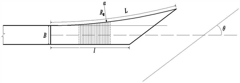
[0030] The maximum operating water head of a vent hole in a project is 120m, the end width of the vent hole is B=6m, and the maximum single-width flow rate is q=120m 3 / s.m, the angle between the central axis of the vent hole and the central line of the downstream channel θ=12°. The asymmetrical stilling basin with single-sided side wall diffusion is used for underflow energy dissipation at the outlet of the vent hole end of the medium-high head hydropower station.
[0031] The asymmetrical stilling pool diffused by the single-side side wall has a structure such as figure 1 , figure 2 As shown, it is composed of a sill, the bottom plate of the stilling pool connected to the downstream of the sill, and the side walls on both sides of the bottom plate of the stilling pool. The bottom plate of the stilling pool is connected by a straight section, an arc section, and a slope section in sequence along the water flow direction. The end of the slope section is an oblique cut. The...
Embodiment 2
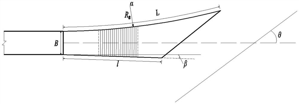
[0035] The maximum operating water head of a vent hole in a project is 100m, the end width of the vent hole is B=6m, and the maximum single-width flow rate is q=100m 3 / s.m, the angle between the central axis of the vent hole and the central line of the downstream channel θ=20°. The asymmetrical stilling basin with double-sided side wall diffusion is used for underflow energy dissipation at the outlet of the vent tunnel end of the medium-high head hydropower station.
[0036] The asymmetrical stilling pool diffused by the single-side side wall has a structure such as image 3 , Figure 4 As shown, it is composed of a sill, the bottom plate of the stilling pool connected to the downstream of the sill, and the side walls on both sides of the bottom plate of the stilling pool. The bottom plate of the stilling pool is connected by a straight section, an arc section, and a slope section in sequence along the water flow direction. The end of the slope section is an oblique cut. T...
Embodiment 3
[0040] The maximum operating water head of a vent hole in a project is 70m, the end width of the vent hole is B=6m, and the maximum single-width flow rate is q=80m 3 / s.m, the included angle θ=30° between the central axis of the vent hole and the central line of the downstream channel. The asymmetrical stilling basin with double-arc diffusion is used for underflow energy dissipation at the outlet of the vent tunnel end of the medium-high head hydropower station.
[0041] The asymmetrical stilling pool diffused by the single-side side wall has a structure such as Figure 5 , Image 6 As shown, it is composed of a sill, the bottom plate of the stilling pool connected to the downstream of the sill, and the side walls on both sides of the bottom plate of the stilling pool. The bottom plate of the stilling pool is connected by a straight section, an arc section, and a slope section in sequence along the water flow direction. The end of the slope section is an oblique cut. The or...
PUM
 Abstract
Description
Claims
Application Information
 - R&D
- Intellectual Property
- Life Sciences
- Materials
- Tech Scout
- Unparalleled Data Quality
- Higher Quality Content
- 60% Fewer Hallucinations
Browse by: Latest US Patents, China's latest patents, Technical Efficacy Thesaurus, Application Domain, Technology Topic, Popular Technical Reports.
© 2025 PatSnap. All rights reserved.Legal|Privacy policy|Modern Slavery Act Transparency Statement|Sitemap|About US| Contact US: help@patsnap.com


