Linear motor braking method and device as well as tactile feedback system

A linear motor and braking device technology, applied in the control system, motor generator control, motor/generator/inverter limiter, etc., can solve the limitation, cannot monitor individual parameter fluctuations and environmental changes, and cannot achieve optimal Questions like the fastest brakes

Active Publication Date: 2017-08-08
AAC TECH PTE LTD
View PDF4 Cites 16 Cited by
  • Summary
  • Abstract
  • Description
  • Claims
  • Application Information

AI Technical Summary

Problems solved by technology

There is no feedback control in this kind of tactile feedback system, so it cannot monitor and feedback the fluctuation of individual parameters and environmental changes
In the prior art, there is a linear motor braking device with feedback control, which uses default voltage and waveform to control the linear motor braking, which cannot achieve optimal and fastest braking; when the vibration is small, the accuracy of the driving voltage itself, The sampling rate and its subtle changes, the number of voltage bits, optimized measurement devices, and deviations due to environmental changes limit the effect of further controlling the driving waveform to implement braking
In addition, this kind of feedback control can only be based on the tracking of F0, and can only be driven in a part of the cycle, which leads to the completion of the braking work after several cycles, and the stability is not good

Method used


Image

  • Linear motor braking method and device as well as tactile feedback system
  • Linear motor braking method and device as well as tactile feedback system
  • Linear motor braking method and device as well as tactile feedback system

Examples


Embodiment 1

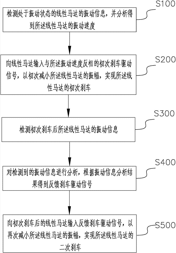
[0039] Such as image 3 As shown, the present invention proposes a linear motor braking method. The linear motor in the present invention can also be called a linear motor, a linear motor or a linear motor. The linear motor includes a stator and a vibrator, including a vibrator and a stator. The stator can be driven to generate an induced magnetic field structure, and the vibrator interacts with the stator to generate an induced electromotive force. The braking of the linear motor in the present invention is a process in which the stator is driven by the braking drive signal to generate an induced magnetic field opposite to the original induced magnetic field, thereby driving the vibrator to weaken the vibration and reduce the amplitude.

[0040] The present invention specifically comprises the following steps:

[0041] S100: Detect vibration information of a linear motor in a vibrating state, and analyze to obtain a vibration velocity of the linear motor. Wherein, the vibra...

Embodiment 2

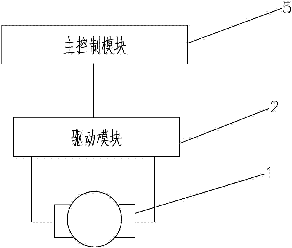
[0050] Such as Figure 5 As shown, the present invention proposes a linear motor brake device, which includes a linear motor 1 , a drive module 2 , a detection module 3 , a feedback control module 4 and a main control module 5 .

[0051] The detection module 3 is connected with the main control module 5 and the feedback control module 4 for detecting the vibration information of the linear motor 1 and sending the vibration information to the feedback control module 4 . Wherein, the vibration information is the vibration speed and / or the vibration acceleration of the linear motor and / or the back electromotive force generated when the linear motor vibrates. Correspondingly, the detection module 3 may be a speed sensor for detecting the vibration speed of the linear motor; the detection module may also be an acceleration sensor for detecting the vibration acceleration of the linear motor; the detection module may also be an electromotive force sensor for To detect the back elect...

Embodiment 3

[0060] Such as Figure 6 As shown, it is a linear motor braking device proposed by the present invention. The difference between this embodiment and Embodiment 2 is that the feedback control module 4 is connected to the main control module 5 . When working, the feedback control module 4 not only sends the feedback brake control signal to the drive module 2, but also sends the feedback brake control signal to the main control module 5, and the main control module 5 stores the feedback brake control signal. In this embodiment, the main control module 5 stores the feedback brake control signal generated each time, so as to monitor the working status of the feedback control device 2 and the linear motor 1 at any time, and can control all the stored feedback brake control signals and the linear motor brake. The vibration information detected in the process is combined and analyzed to obtain the optimal feedback control signal of the linear motor, that is, driven by the feedback con...


PUM


Abstract

The invention provides a linear motor braking method and device as well as a tactile feedback system. The braking method comprises the steps as follows: S100, detecting vibration information of a linear motor in a vibration state and obtaining the vibration speed of the linear motor through analysis; S200, inputting an initial braking driving signal having the opposite phase with the vibration speed to the linear motor so as to reduce the amplitude of the linear motor initially and realize initial braking of the linear motor; S300, detecting the vibration information of the linear motor after initial braking; S400, analyzing the vibration information detected in S300 and obtaining a feedback braking driving signal according to an analysis result of the vibration information; S500, inputting the feedback braking driving signal to the linear motor after initial braking to reduce the amplitude of the linear motor again and realize secondary braking of the linear motor. With the adoption of the method, quick reduction of the amplitude of the linear motor can be realized, the braking time can be shortened, and the quick braking function of the linear motor can be realized when the amplitude of the linear motor is very small.

Description

technical field [0001] The invention belongs to the field of linear motors, and in particular relates to a linear motor braking method, a linear motor braking device and a tactile feedback system with the linear motor braking device. Background technique [0002] Due to its superior performance of small size, quick start, and fast braking, linear motors are more and more widely used in vibration feedback applications, and are often used to simulate various vibration situations. In various applications, there is a kind of situation that requires the vibration of the linear motor to achieve fast braking, but the acceleration of the linear motor is often very slow to stop. figure 1 A linear motor braking device in the prior art is shown. This kind of device generally includes a main control module 5 , a driving module 2 connected to the main control module 5 and a linear motor 1 connected to the driving module 2 . There is no feedback control in this kind of tactile feedback ...

Claims


Application Information

Patent Timeline
Patent Type & Authority Applications(China)
IPC IPC(8): G06F3/01H02P3/18
CPCG06F3/016H02P3/18
Inventor 司宏伟谢兵蒋亮
Owner AAC TECH PTE LTD
Why Eureka
Try Eureka