
Backlight brightness adjustment circuit, backlight brightness adjustment system and method

A technology for luminous brightness and circuit adjustment, applied to electrical components, static indicators, instruments, etc., can solve the problem that the difference in luminous brightness of the backlight cannot be compensated, and achieve the effect of improving uniformity

Active Publication Date: 2019-06-21
BOE TECH GRP CO LTD
View PDF5 Cites 0 Cited by
  • Summary
  • Abstract
  • Description
  • Claims
  • Application Information

AI Technical Summary

Problems solved by technology

Commonly used backlight sources include light emitting diodes (Light Emitting Diode, referred to as LED). For large-size liquid crystal displays, the backlight source usually includes multiple partitions, and each partition includes an LED circuit. In the prior art, only by adjusting different The pulse width modulation signal (Pulse Width Modulation, referred to as PWM) corresponding to the LED circuit of the partition is used to adjust the luminance of each partition, but it cannot compensate for the difference in luminance between different partitions of the backlight, which affects the uniformity of the luminance of the backlight

Method used


Image

  • Backlight brightness adjustment circuit, backlight brightness adjustment system and method
  • Backlight brightness adjustment circuit, backlight brightness adjustment system and method
  • Backlight brightness adjustment circuit, backlight brightness adjustment system and method

Examples


Embodiment 1

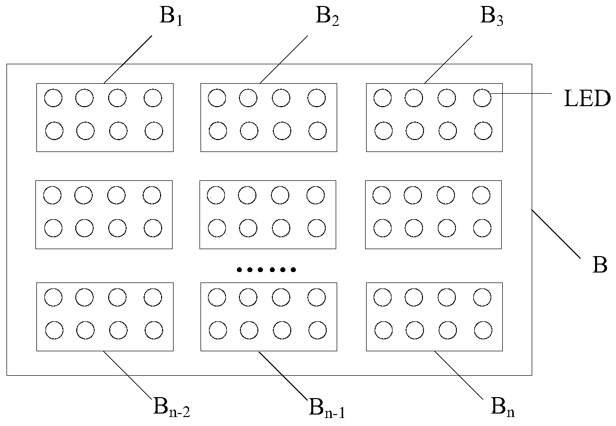
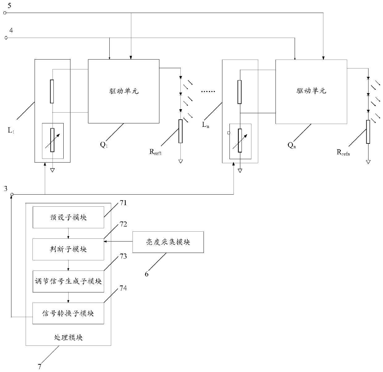
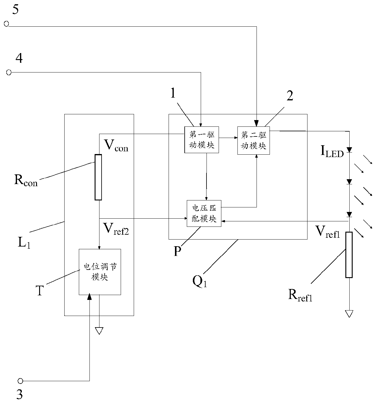
[0040] An embodiment of the present invention provides a backlight brightness adjustment circuit, such as figure 1 As shown, backlight B includes multiple sub-backlight partitions B 1 , B 2 ,...B n-1 , B n , where each sub-backlight partition includes an LED loop, such as figure 2 As shown, the backlight brightness adjustment circuit includes a plurality of brightness adjustment units L 1 ,...,L n , multiple drive units Q for driving LEDs 1 ,...,Q n and multiple grounded sense resistors R ref1 ,...,R refn ; Among them, the sub-backlight partition, the brightness adjustment unit, the drive unit and the sampling resistor correspond one-to-one; the following sub-backlight partition B 1 Corresponding brightness adjustment unit L 1 , drive unit Q 1 and the sampling resistor R ref1 As an example, the structure of the backlight brightness adjustment circuit is described, such as image 3 As shown, the drive unit Q 1 Including voltage matching module P, brightness adjus...

Embodiment 2

[0053] like figure 2 As shown, the present embodiment provides a backlight brightness adjustment system, including: a brightness acquisition module 6, a processing module 7 and the backlight brightness adjustment circuit provided in Embodiment 1; the output terminal of the brightness acquisition module 6 and the processing module 7 The input terminals of the processing module 7 are connected to each other, and the output terminals of the processing module 7 are connected to the input terminals of a plurality of brightness adjustment units of the backlight brightness adjustment circuit; wherein,

[0054] Brightness collection module 6 is used for collecting the luminous brightness information of multiple sub-backlight source partitions;

[0055] The processing module 7 is used to obtain a brightness uniformity adjustment signal according to the luminous brightness information of the plurality of sub-backlight sub-regions and the preset backlight luminous brightness information...

Embodiment 3

[0068] see Figure 4 , this embodiment provides a method for adjusting the luminance of a backlight source, including:

[0069] S100: collecting luminance information of multiple sub-backlight source partitions;

[0070] S200: Obtain a brightness uniformity adjustment signal according to the luminous brightness information of the plurality of sub-backlight source partitions and the luminous brightness information of the preset backlight source;

[0071] S300: According to the brightness uniformity adjustment signal, adjust the luminance of the plurality of sub-backlight sub-regions, so that the luminance of the plurality of sub-backlight sub-regions reaches a preset luminance of the backlight source.

[0072] The beneficial effect of the method for adjusting the brightness of the backlight source provided in this embodiment is the same as that of the system for adjusting the brightness of the backlight source provided in the second embodiment above, and will not be repeated h...


PUM


Abstract

The invention discloses a backlight luminance adjustment circuit, a backlight luminance adjustment system and a method, relate to the field of display technology, and are used for improving the uniformity of the backlight luminance. The backlight brightness adjustment circuit includes: a plurality of brightness adjustment units, a plurality of drive units for driving LEDs and a plurality of grounded sampling resistors; each drive unit includes a voltage matching module; each brightness adjustment unit includes a grounded The potential adjustment module; the voltage matching module is used to make the voltage at both ends of the potential adjustment module equal to the voltage at both ends of the sampling resistor. The backlight brightness adjustment system includes the backlight brightness adjustment circuit. The method for adjusting the brightness of the backlight source includes the above-mentioned circuit for adjusting the brightness of the backlight source. The brightness adjustment circuit of the backlight source provided by the present invention is used for adjusting the brightness of the backlight source.

Description

technical field [0001] The present invention relates to the field of display technology, in particular to a backlight luminance adjustment circuit, a backlight luminance adjustment method and a system. Background technique [0002] Liquid crystal display is a flat and ultra-thin display device. Since liquid crystal itself does not have the characteristic of emitting light, the backlight module becomes an indispensable and important part of liquid crystal display. [0003] In the prior art, a backlight module includes a backlight and a backlight driving circuit for driving the backlight. Commonly used backlight sources include light emitting diodes (Light Emitting Diode, referred to as LED). For large-size liquid crystal displays, the backlight source usually includes multiple partitions, and each partition includes an LED circuit. In the prior art, only by adjusting different The pulse width modulation signal (Pulse Width Modulation, PWM for short) corresponding to the LED ...

Claims


Application Information

Patent Timeline
Patent Type & Authority Patents(China)
IPC IPC(8): G09G3/34G09G3/36
CPCG09G3/3406G09G3/36G09G2360/145H05B45/12H05B45/46
Inventor 陈硕
Owner BOE TECH GRP CO LTD
Learn More