Clutch mechanism for driving system of washing machine and driving system of washing machine

A technology of drive system and clutch mechanism, which is applied in the field of washing machines, can solve the problems of cumbersome connection structure between the clutch and the rotor, the structure is not compact enough, and the cost of the motor is high, so as to achieve the effects of easy batch assembly, low cost, and reduced installation volume

Inactive Publication Date: 2019-11-26
CHANGZHOU XINYA ELECTROMOTOR
View PDF8 Cites 0 Cited by
  • Summary
  • Abstract
  • Description
  • Claims
  • Application Information

AI Technical Summary

Problems solved by technology

However, because this technology uses a permanent magnet outer rotor brushless DC motor, the cost of the motor is high, and the connection structure between the clutch and the rotor is cumbersome. There are many parts, complex connection, high cost, and not compact enough structure. It is also not suitable for low-end washing machines used by families.

Method used


Image

  • Clutch mechanism for driving system of washing machine and driving system of washing machine
  • Clutch mechanism for driving system of washing machine and driving system of washing machine
  • Clutch mechanism for driving system of washing machine and driving system of washing machine

Examples


Embodiment Construction

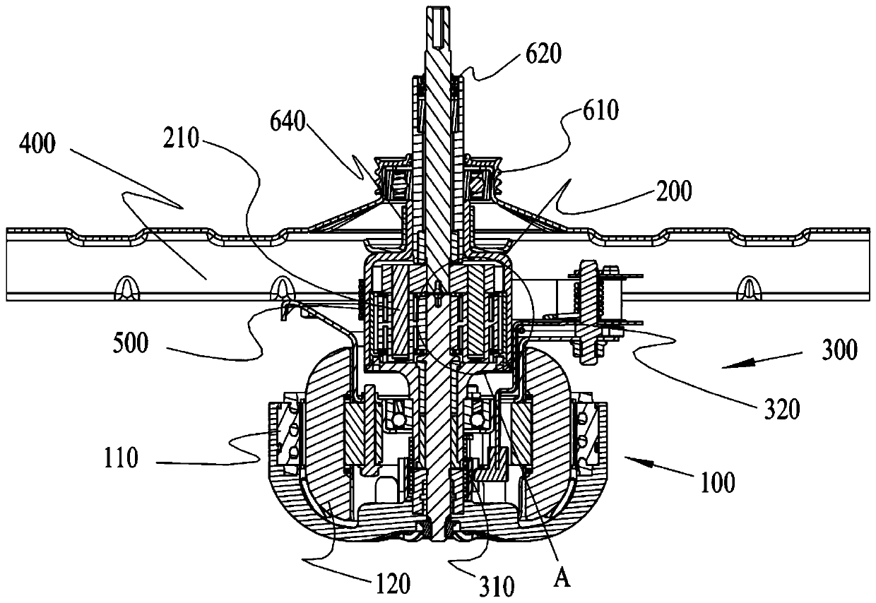
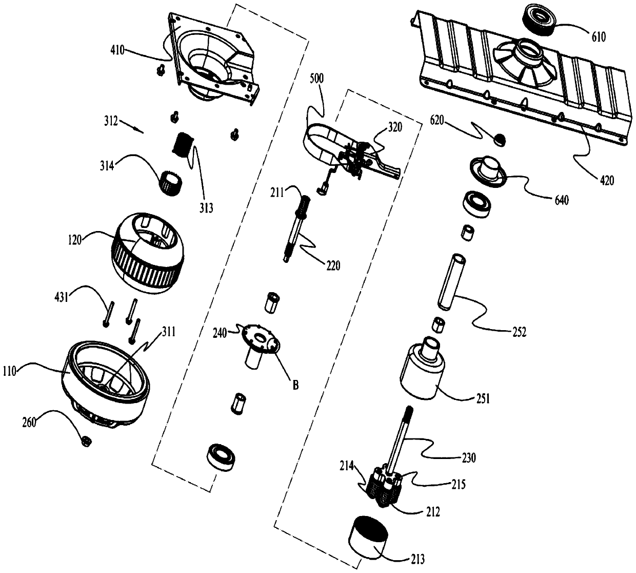
[0059] The embodiment of the present invention discloses a clutch mechanism for a washing machine drive system, which includes a clutch assembly and a lever assembly, and selectively transmits driving force to the clutch assembly through the lever assembly, so that the drive shaft and the drive sleeve are in a separated state and a locked state The clutch assembly is provided with a clutch shaft sleeve and a wrapping spring assembly, and the clutch shaft sleeve is arranged outside the input end of the drive shaft of the washing machine drive system, and is fixedly connected with the rotating body of the washing machine drive system; the wrap spring assembly includes a spiral spring and a sleeve The ratchet is connected to the outside of the coil spring, and the coil spring is sleeved on the outside of the input end of the clutch sleeve and the drive sleeve; wherein, the ratchet includes the first ratchet and the second ratchet coaxially sleeved on the outside of the coil spring ...


PUM


Abstract

The invention discloses a clutch mechanism used for a washing machine driving system and the washing machine driving system. The clutch mechanism comprises a clutch assembly and a shift lever assembly, and the clutch assembly is provided with a clutch shaft sleeve and a wrapping spring assembly; the wrapping spring assembly comprises a spiral spring and a ratchet wheel, wherein the spiral spring is sleeved with the ratchet wheel. The ratchet wheel comprises a first ratchet wheel body and a second ratchet wheel body which are coaxially connected to the outer side of the spiral spring in a sleeving mode and different in ratchet wheel taper direction, one end of the spiral spring is limited on the first ratchet wheel body, and the other end of the spiral spring is limited on the second ratchet wheel body. The shift lever assembly comprises a shift fork assembly which is arranged on the outer side of the ratchet wheel in a sleeving mode and installed on an installation shell of the washing machine driving system, and the shift fork assembly is provided with first ratchet thorns meshed with the first ratchet wheel body and second ratchet thorns meshed with the second ratchet wheel body. The clutch mechanism is simple in structure and convenient to control, by the adoption of the double-ratchet-wheel and double-ratchet-thorn meshing drive clutch mode, the two ends of the wrapping spring assembly are loosened, and the clutch state switching precision can be further effectively ensured.

Description

technical field [0001] The invention relates to the field of washing machines, in particular to a clutch mechanism for a washing machine driving system. The invention also relates to a washing machine driving system to which the clutch mechanism is applied, and is especially suitable for middle and low-end washing machines used by families. Background technique [0002] The main work of the washing machine is to drive the pulsator to rotate by the driving mechanism, agitate the water flow and rotate the clothes, so as to achieve the purpose of washing clothes. At present, the power source of the commonly used driving mechanism is a motor, and the torque when the motor rotates is transmitted to the reduction device by the output shaft of the motor, and then the output shaft of the reduction device is connected with the pulsator, thereby driving the pulsator to rotate. [0003] Ordinary motors have a relatively high speed. In order to obtain a suitable output speed, the motor ...

Claims


Application Information

Patent Timeline
Patent Type & Authority Patents(China)
IPC IPC(8): D06F37/40
CPCD06F37/40
Inventor 刘晓辉费亚德巴妮萨刘海荣
Owner CHANGZHOU XINYA ELECTROMOTOR
Why Eureka
Try Eureka