
Super heat preservation press connection exposed frame unit body curtain wall system

A unit body and exposed frame technology, applied to walls, building components, buildings, etc., can solve problems such as easy heat exchange, non-compliance with environmental protection and energy saving, and influence on the unit structure of curtain walls, achieving good results, ensuring thermal insulation performance, and good environmental protection Effect

Inactive Publication Date: 2017-08-11
GRAND FACADE DECORATION ENG CO LTD
View PDF0 Cites 2 Cited by
  • Summary
  • Abstract
  • Description
  • Claims
  • Application Information

AI Technical Summary

Problems solved by technology

[0004] In such a structured exposed frame glass curtain wall, the series of connections between beams and columns-mounting parts-pressing plates are screw connections, and when two exposed frame units are docked, there must be a certain gap between them, and the heat in the room or the outside world The heat will enter from the gap, and heat exchange will easily occur indoors or outdoors, which will affect the structure of the curtain wall unit body, and at the same time, it will easily produce heat exchange, which does not meet the current needs of environmental protection and energy saving.

Method used


Image

  • Super heat preservation press connection exposed frame unit body curtain wall system
  • Super heat preservation press connection exposed frame unit body curtain wall system
  • Super heat preservation press connection exposed frame unit body curtain wall system

Examples


Embodiment 2

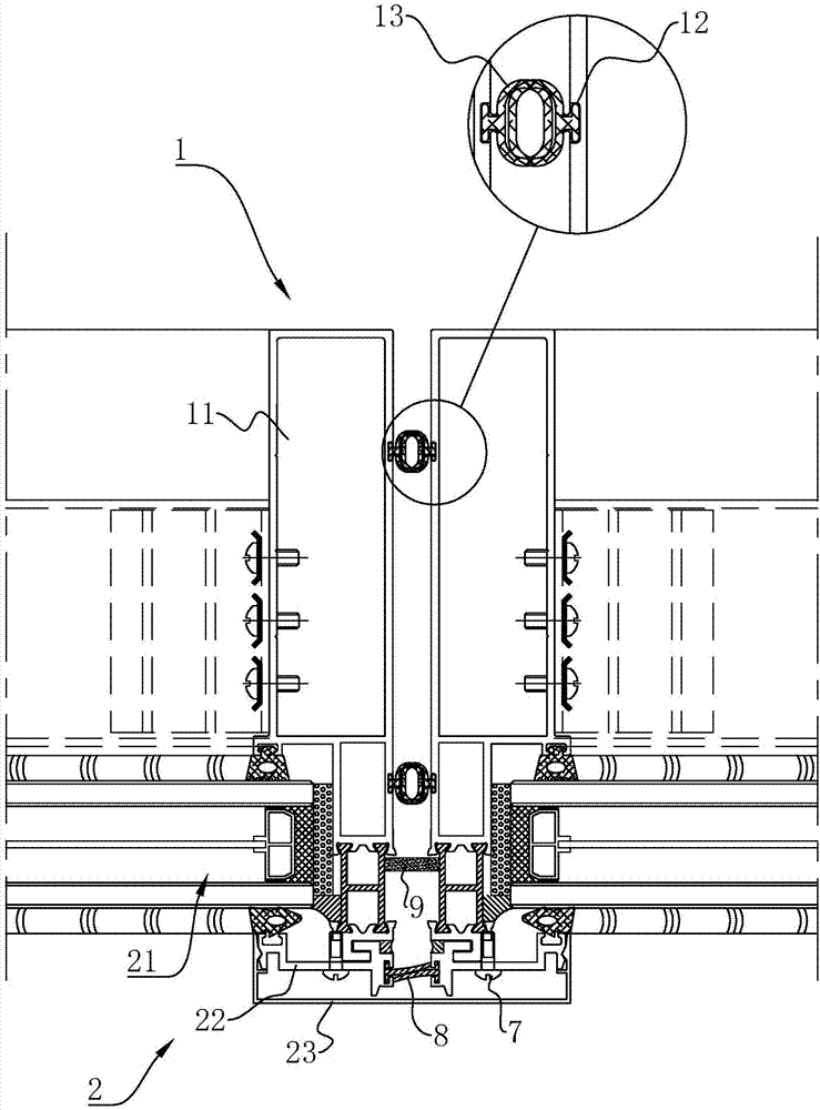
[0050] Embodiment 2: The difference from Embodiment 1 is that, as figure 1 and Figure 4 As shown, the heat-insulation strip 9 includes a first heat-insulation strip 91 and two second heat-insulation strips 92 respectively bonded to the heat-insulation strip 4 in one side of the exposed frame unit 1, and the two second An inserting groove 93 is formed between the heat insulating strips 92 , and when two exposed frame units 1 are butted and installed, the first heat insulating strip 91 is inserted into the inserting groove 93 .

Embodiment 3

[0051] Embodiment three: the difference from embodiment two is that, as figure 1 and Figure 5 As shown, the heat insulating rubber strip 9 includes a first wedge-shaped strip 100 formed with a first slope 1001 at one end and a second wedge-shaped strip 101 with a second slope 1011 formed at one end matching the first wedge-shaped strip 100. When two bright frame units 1 are docked, the first wedge-shaped strip 100 and the second wedge-shaped strip 101 are connected in relative contact, and the first slope surface 1001 and the second slope surface 1011 have the same angle and are in close contact.

Embodiment 4

[0052] Embodiment 4: The difference from Embodiment 3 is that, as figure 1 and Figure 6 As shown, the heat insulating strip 9 includes a connection section 200 bonded to the heat insulating strip 4 and a butt section 201 fixedly connected to one end away from the heat insulating strip 4 and bifurcated to both sides. The section of the heat insulating strip 212 is In a "Y" shape, when two exposed frame units 1 are docked, the docking sections 201 are connected to each other to close the gap and cut off the heat conduction between indoor and outdoor.


PUM


Abstract

The invention discloses a curtain wall system of super thermal insulation crimping exposed frame units, which comprises at least two mutually symmetrical exposed frame units, the exposed frame units include upright columns and thermal insulation structure parts, the upright columns are bonded and fixed to each other, the The thermal insulation structure part includes the exposed frame pressing plate, the hollow glass layer clamped between the exposed frame pressing plate and the column; the curtain wall system also includes a decorative buckle cover, which is fastened outside the two exposed frame pressing plates; the exposed frame pressing plate Water-blocking adhesive strips are arranged between them; heat-insulating adhesive strips are arranged between the hollow glass layers, and the heat-insulating adhesive strips provided can block the outside world from entering the gap and exchange heat with the room, saving energy and environmental protection.

Description

technical field [0001] The invention relates to the field of curtain wall decoration, more specifically, it relates to a super thermal insulation crimping exposed frame unit body curtain wall system. Background technique [0002] The exposed frame glass curtain wall is usually used for building exterior decoration. On the one hand, it can meet the decorative effect of the building, and on the other hand, it can ensure the heat preservation, sealing, lighting, heat protection and sound insulation of the building. [0003] The curtain wall keel of the existing exposed frame glass curtain wall consists of columns and beams, and is fixed by a pressing plate between the glass plates, and the pressing plate is connected to the mounting parts installed on the columns or beams. [0004] In such a structured exposed frame glass curtain wall, the series of connections between beams and columns-mounting parts-pressing plates are screw connections, and when two exposed frame units are d...

Claims


Application Information

Patent Timeline
IPC IPC(8): E04B2/96
CPCE04B2/96
Inventor 冯华国赵红德
Owner GRAND FACADE DECORATION ENG CO LTD
Learn More