Lamp strip press-fit device

A technology of pressing device and light bar, applied in lighting devices, lighting device parts, light source fixing and other directions, can solve the problems affecting the quality of backlight modules, light leakage, pollution of light bars, etc., to reduce the scrap rate, reduce The effect of artificial pollution and preventing false start

Pending Publication Date: 2017-08-11
博讯光电科技(合肥)有限公司
View PDF10 Cites 4 Cited by
  • Summary
  • Abstract
  • Description
  • Claims
  • Application Information

AI Technical Summary

Problems solved by technology

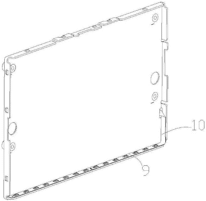
[0002] At present, the backlight module includes the light bar, the double-sided tape of the light bar, and the back plate. When the existing light bar is combined with the back plate, the light bar needs to be pressed to the back plate. The manual pressing currently used is likely to cause floating and pollution. Or the problem of damage to the light bar; the pressing device used needs to press the light bar to the two sides of the back panel twice. Specifically, the back panel is fixed first, and the light bar is pressed on one side of the back panel through the device. Side, after the pressing is completed, manually rotate the back panel, reposition, and then press the other side of the device through the device light bar
[0003] The above-mentioned light bar pressing device needs two positionings, there may be errors between the two positionings, and the problem of poor accuracy occurs. At the same time, two separate pressings will cause a gap between the light bar and the backplane bracket, which will affect the quality of the backlight module. Lead to the appearance of light leakage, resulting in the display quality of the display device

Method used


Image

  • Lamp strip press-fit device
  • Lamp strip press-fit device
  • Lamp strip press-fit device

Examples


Embodiment Construction

[0017] In the description of the present invention, unless otherwise specified, the orientations or positional relationships indicated by the terms "up", "down", "left", "right", "front", "rear" etc. are based on the position when standing at the start button position in the drawings The orientation or positional relationship is only for describing the present invention and simplifying the description, but does not indicate or imply that the referred device or structure must have a specific orientation, and thus should not be construed as a limitation of the present invention. In addition, the terms "first", "second", etc. are used for descriptive purposes only, and should not be construed as indicating or implying relative importance.

[0018] The following preferred embodiments of the present invention will be further described in detail in conjunction with the accompanying drawings. The following preferred modes are used to illustrate the utility model and are not intended t...


PUM


Abstract

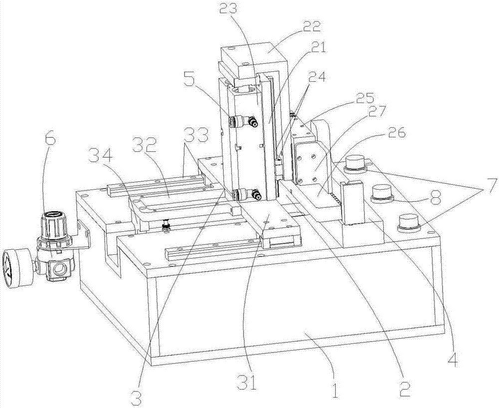
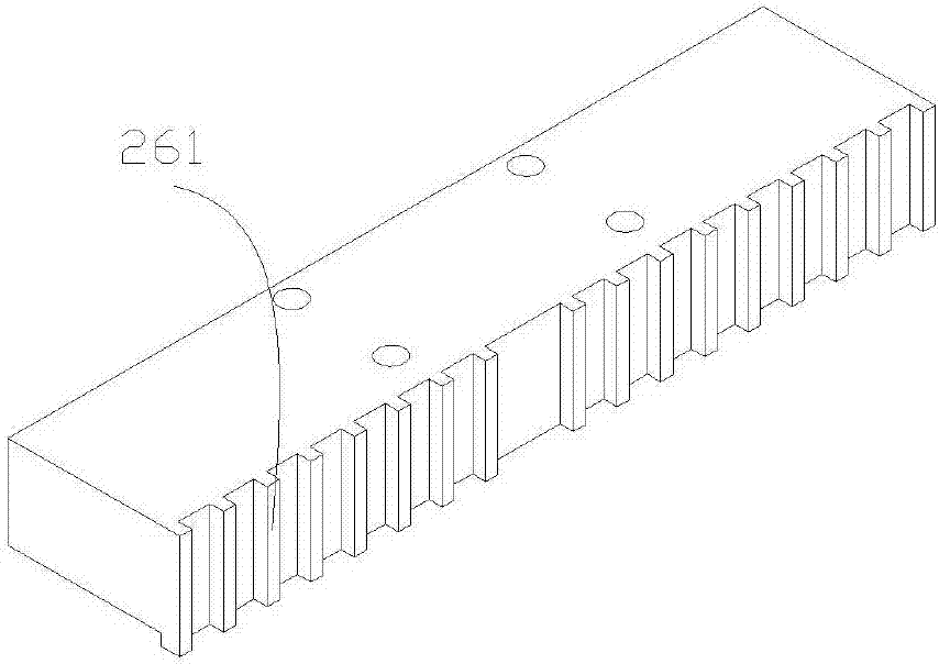
The invention provides a lamp strip press-fit device. The device comprises a box body and a press-fit structure which is arranged on the box body and used for pressing a lamp strip; the press-fit structure comprises a vertical fixing plate, an inverted-L-shaped plate connected with the rear side of the vertical fixing plate, a longitudinal drive mechanism connected with the front side of the vertical fixing plate and a transverse drive mechanism connected with the side edge of the inverted-L-shaped plate, the press-fit structure further comprises a horizontal pressing plate arranged on the lower side of the transverse drive mechanism and a side pressing plate arranged on the side edge of the transverse drive mechanism, and a sliding structure enabling the press-fit structure to move between the to-be-pressed state and the press-fit state is connected between the press-fit structure and the box body and is driven through the horizontal driving mechanism. The device is connected with a dual-starting and resetting button through a PLC, the horizontal drive mechanism, the longitudinal drive mechanism and the transverse drive mechanism are sequentially controlled to drive the horizontal pressing plate and the side pressing plate to carry out press fit on the lamp strip, the device is simple in structure, convenient to operate and high in alignment precision, the lamp strip press-fit intensityis balanced, and the product quality is ensured.

Description

technical field [0001] The invention relates to the technical field of backlight production, and in particular designs a light bar pressing device, in particular, a light bar and a backboard bonding and fixing device. Background technique [0002] At present, the backlight module includes the light bar, the double-sided tape of the light bar, and the back plate. When the existing light bar is combined with the back plate, the light bar needs to be pressed to the back plate. The manual pressing currently used is likely to cause floating and pollution. Or the problem of damage to the light bar; the pressing device used needs to press the light bar to the two sides of the back panel twice. Specifically, the back panel is fixed first, and the light bar is pressed on one side of the back panel through the device. On the side, after the pressing is completed, manually rotate the back panel, reposition, and then press the other side of the device through the device light bar. [0...

Claims


Application Information

Patent Timeline
Patent Type & Authority Applications(China)
IPC IPC(8): F21V19/00
CPCF21V19/00
Inventor 曹颖
Owner 博讯光电科技(合肥)有限公司
Why Eureka
Try Eureka