Rock joint sample direct shearing test box

A rock joint and shear box technology, which is applied in the direction of applying stable shear force to test the strength of materials, measuring devices, instruments, etc., can solve the problem of unsatisfactory anti-friction effect and difficulty in accurately measuring the normal shear dilation of rock joints. Quantity, shear strength, etc.

Inactive Publication Date: 2017-08-11
TONGJI UNIV
View PDF3 Cites 14 Cited by
  • Summary
  • Abstract
  • Description
  • Claims
  • Application Information

AI Technical Summary

Problems solved by technology

[0003] 1) During the shearing process of rock joints, especially under high normal load conditions, the upper shear box in the existing direct shear box will move vertically relative to the lower shear box (upward flipping phenomenon) , changing the stress conditions at both ends of the rock joint, thus affecting the accuracy of the rock joint shear test results;
[0004] 2) During the rock joint shearing process, there will be sliding friction between the inner wall of the upper shear box of the rock joint and the rock joint sample, which makes it difficult to accurately m

Method used


Image

  • Rock joint sample direct shearing test box
  • Rock joint sample direct shearing test box
  • Rock joint sample direct shearing test box

Examples


Embodiment 1

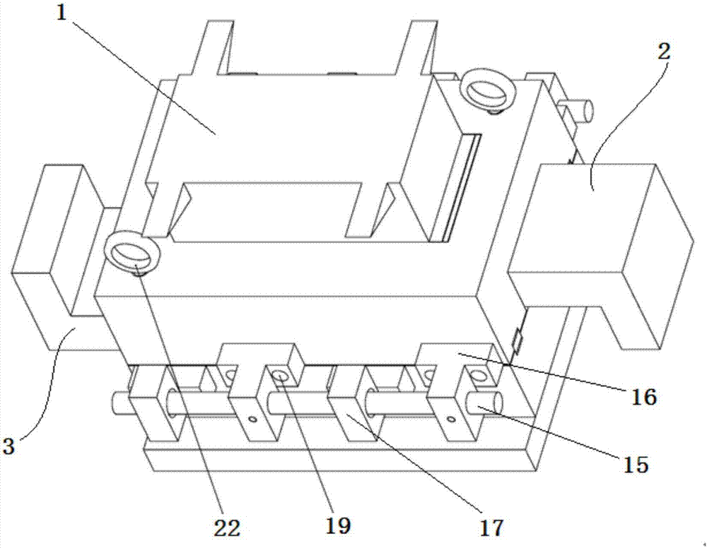
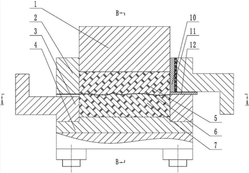
[0038] A rock joint sample direct shear test box, its structure is as follows Figure 1 ~ Figure 4 As shown, it includes a normal loading pad 1 , an upper shear box 2 , a lower shear box 3 and a base 4 . The upper shear box 2 and the lower shear box 3 form a cavity for placing a rock joint sample, and the rock joint sample is composed of an upper joint block 5, a joint 6 and a lower joint block 7.

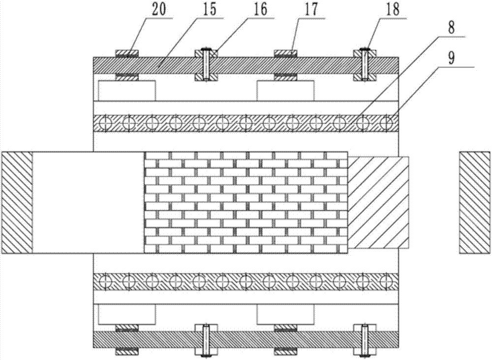
[0039] The structure of the upper shear box 2 and the lower shear box 3 is as follows Figure 5As shown, each includes a horizontal plate 27 and an L-shaped block 28 arranged at one end of the horizontal plate 27. The center of the horizontal plate 27 is provided with a groove 29 for placing rock joint samples, and one end of the groove 29 is covered by an L-shaped block. Block 28 is closed, and both sides of horizontal plate 27 are all provided with guide groove 271 along the lengthwise direction; groove 29, and the height of the horizontal stopper 281 is less than the depth of ...


PUM


Abstract

The invention relates to a rock joint sample direct shearing test box. The test box comprises a base, an upper shearing box and a lower shearing box which are used for placing a rock joint sample and a normal loading cushion block presses upon an upper joint block of a rock. A fixing support arranged downward is installed on the upper shearing box, a bearing support arranged upward is installed on the lower shearing box, a guiding rod is inserted into the fixing support and the bearing support in a penetrating mode, pin holes are formed in the fixing support, the guiding rod and the fixing support are fixed through a locating pin, and a linear motion bearing used for connecting the guiding rod with the bearing support is arranged in the slot of the bearing support. Compared with the prior art, by means of the test box, not only can free motion of the lower shearing box in the shearing direction in the rock joint sample shearing process be guaranteed, but also the problem that the upper shearing box is reversed upward is effectively solved; contact friction between the upper and lower shearing boxes in the rock joint sample shearing process and friction between the upper shearing box and the upper joint block of the rock are effectively reduced, so that the shearing process is more in line with the real condition.

Description

technical field [0001] The invention relates to geotechnical engineering test equipment, in particular to a rock joint sample direct shear test box. Background technique [0002] The joint plane in rock mass is an important factor controlling the stability of rock mass engineering. The research on its shear mechanical properties has always been the focus of attention in the industry. How to accurately obtain the strength and deformation characteristics of rock joints has become a major issue for technical personnel engaged in rock engineering. greatest difficulty faced. The indoor direct shear test (direct shear test for short) is the most direct and effective means to study the shear mechanical properties of rock mass joints. Traditional rock joint shearing instruments mainly have the following three problems: [0003] 1) During the shearing process of rock joints, especially under high normal load conditions, the upper shear box in the existing direct shear box will move...

Claims


Application Information

Patent Timeline
IPC IPC(8): G01N3/24G01N3/02
CPCG01N3/24G01N3/02G01N2203/0025
Inventor 钱鑫夏才初桂洋刘文礼庄小清喻强锋
Owner TONGJI UNIV
Why Eureka
Try Eureka