Supercharge Your Innovation With Domain-Expert AI Agents!

Spliced screen and back projection unit

A splicing screen and screen technology, applied in optics, instruments, projection devices, etc., can solve the problems of splicing screen discontinuity and poor display effect of splicing screen, and achieve the effect of good display effect and avoiding discontinuity.

Inactive Publication Date: 2017-08-11
HISENSE
View PDF7 Cites 7 Cited by
  • Summary
  • Abstract
  • Description
  • Claims
  • Application Information

AI Technical Summary

Problems solved by technology

[0006] In order to solve the problem of discontinuity in the splicing screen in the prior art when displaying images, which leads to poor display effect of the splicing screen, an embodiment of the present invention provides a splicing screen and a rear projection unit

Method used


Image

  • Spliced screen and back projection unit
  • Spliced screen and back projection unit
  • Spliced screen and back projection unit

Examples


Embodiment Construction

[0041] In order to make the object, technical solution and advantages of the present invention clearer, the implementation manner of the present invention will be further described in detail below in conjunction with the accompanying drawings.

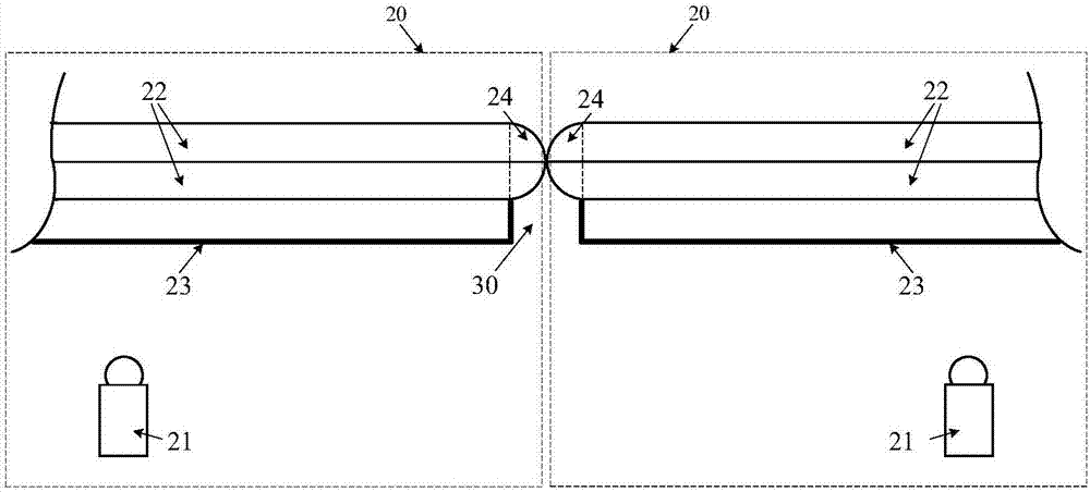
[0042] An embodiment of the present invention provides a splicing screen, such as diagram 2-1 as shown, diagram 2-1 It is a schematic structural diagram of a splicing screen provided by an embodiment of the present invention, and the splicing screen may include:

[0043] A plurality of screens 22 arranged in an array and protruding structures 24 provided at the adjacent edges of every two adjacent screens 22 .

[0044] Wherein, the protruding structures 24 at adjacent edges of every two adjacent screens 22 abut against each other, and the refractive index of the protruding structures 24 is greater than that of air. In practical applications, no protruding structure 24 is provided at the non-adjacent edges of every two adjacent scre...


PUM


Abstract

The invention discloses a splicing screen and a rear projection unit, belonging to the technical field of display. The splicing screen includes: a plurality of screens arranged in an array and a raised structure arranged at the adjacent edges of every two adjacent screens; wherein, the adjacent edges of every two adjacent screens The raised structure abuts against the raised structure, the raised structure having a refractive index greater than that of air. By arranging a raised structure at the edge of the screen, light is emitted from the splicing gap, which avoids the discontinuity of the displayed image on the splicing screen, and thus makes the display effect of the splicing screen better. The invention is used in splicing screens with rear projection units.

Description

technical field [0001] The invention relates to the field of display technology, in particular to a splicing screen and a rear projection unit. Background technique [0002] Projection splicing display, also known as splicing screen, is to splice multi-screen images together to realize ultra-large screen and ultra-high-resolution image display. [0003] Please refer to figure 1 , figure 1 It is a structural schematic diagram of a splicing screen provided in the prior art. The splicing screen is composed of multiple rear projection units 11 closely spliced ​​together, and there is a splicing gap 12 between two adjacent rear projection units 11 . Wherein, each rear projection unit 11 may include a projector 111, a screen 112 and a fixed bracket 113, the screen 112 may be a Fresnel optical screen, and the Fresnel optical screen may include: a Fresnel lens layer 112b and a lenticular lens Layer 112a. In each rear projection unit 11, the light emitted by the projector 111 exi...

Claims


Application Information

Patent Timeline
IPC IPC(8): G03B21/56G03B21/602G03B21/625
CPCG03B21/56G03B21/602G03B21/625
Inventor 李泽广
Owner HISENSE
Features
  • R&D
  • Intellectual Property
  • Life Sciences
  • Materials
  • Tech Scout
  • Unparalleled Data Quality
  • Higher Quality Content
  • 60% Fewer Hallucinations
Learn More