
A power cord layout method for a power control unit

A technology of power control unit and power line, which is applied in the direction of electrical components, circuits, electric solid devices, etc., can solve the problems of difficult wiring scheme, low efficiency, complicated power line connection, etc., and achieve the effect of improving the voltage drop before and after

Active Publication Date: 2018-10-26
RAMAXEL TECH SHENZHEN
View PDF5 Cites 0 Cited by
  • Summary
  • Abstract
  • Description
  • Claims
  • Application Information

AI Technical Summary

Problems solved by technology

[0003] In the layout of the SoC chip, due to the different layout methods of the chip and the different shapes and power consumption requirements of various hard core IPs, there are obvious differences in the method of inserting the power control unit; the connection of the power line is more complicated, and it is not easy to obtain a better solution. connection scheme, and even many places can only be connected manually, which is inefficient and error-prone
As a result, the voltage drop is large and the wiring resources will be underutilized, even hindering the connection of normal signal lines.

Method used

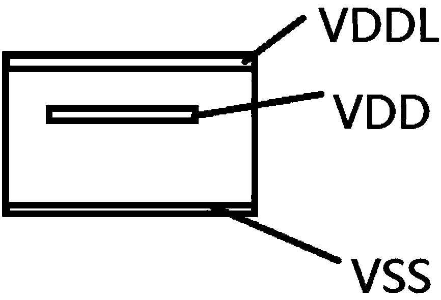
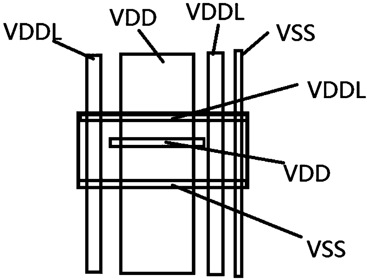
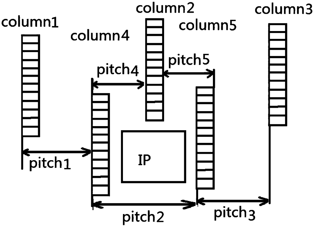

Image

  • A power cord layout method for a power control unit
  • A power cord layout method for a power control unit
  • A power cord layout method for a power control unit

Examples


Embodiment Construction

[0017] The following will clearly and completely describe the technical solutions in the embodiments of the present invention with reference to the accompanying drawings in the embodiments of the present invention. Obviously, the described embodiments are only some, not all, embodiments of the present invention. Based on the embodiments of the present invention, all other embodiments obtained by persons of ordinary skill in the art without creative efforts fall within the protection scope of the present invention.

[0018] Description of related abbreviations: PS refers to power switch cell (power control unit); STD refers to standard cell (standard logic unit); Pitch refers to the distance between units with the same attribute; Layer metal; 1P7M1TM refers to 1 layer of poly, 7 layers of metal and the top layer TM2 is thick metal.

[0019] In this embodiment, the SMIC 40nm 1P7M1TM process is used for illustration. The winding resources of this process include 7 layers of metal...


PUM


Abstract

The invention relates to a power line layout method for power control units. The distance between two power lines at a top metal layer TM2 is selected as a standard distance, the power control units are inserted in columns and placed row by row in each column, the distance between the columns is an integer multiple of the standard distance, and the column distance between the power control units of each column can be adjusted according to the voltage drop requirement and the integer multiple of the standard distance; and the connecting line layer of a power inlet line and a power outlet line is specified strictly, the width of the connecting line is automatically calculated via a script, and the effect of improving the front and back voltage drop of the power control units is achieved by reasonably arranging the positions of the power control units and sufficiently utilizing the winding resource of each layer.

Description

technical field [0001] The invention relates to the field of chip design and manufacture, in particular to a power line layout method for a power control unit. Background technique [0002] With the popularity of portable electronic products, more and more attention is paid to low power consumption design. When certain functions are not needed, it can be considered to turn off the power supply of this part of the logic circuit, so it is necessary to insert a power control unit to switch the power supply of these logic circuits. [0003] In the layout of the SoC chip, due to the different layout methods of the chip and the different shapes and power consumption requirements of various hard core IPs, there are obvious differences in the method of inserting the power control unit; the connection of the power line is more complicated, and it is not easy to obtain a better solution. Even many places can only be connected manually, which is inefficient and error-prone. As a resu...

Claims


Application Information

Patent Timeline
Patent Type & Authority Patents(China)
IPC IPC(8): H01L27/02
CPCH01L27/0207
Inventor 苟帅胡波李华东牛燕贞
Owner RAMAXEL TECH SHENZHEN
Learn More