Multi-groove photocatalyst ceramic plate

A ceramic plate and photocatalyst technology, applied in the field of ceramic plates, can solve the problems of difficult disposal of waste, high cost, inability to handle chemicals, etc., and achieves the effects of easy cleaning, decomposing odors, and preventing dirt from adhering

Pending Publication Date: 2017-08-15
陈楚松 +2
View PDF11 Cites 1 Cited by
  • Summary
  • Abstract
  • Description
  • Claims
  • Application Information

AI Technical Summary

Problems solved by technology

However, because the medicine is used, it itself is used as a consumable, and it is necessary to exchange it regularly, and the cost is high.
Chemicals cannot be treated as general products, and waste disposal is also a problem

Method used


Image

  • Multi-groove photocatalyst ceramic plate
  • Multi-groove photocatalyst ceramic plate

Examples


Embodiment 1

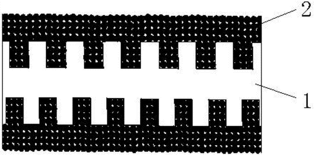
[0026] refer to figure 1 , a kind of porous type photocatalyst ceramic plate, comprises porous type ceramic plate 1, and its thickness is 5mm, and the whole interior of porous type ceramic plate 1 is interconnected by the small hole that size is 50 μ m and is three-dimensional network structure, and its porous type The porosity of the type ceramic plate 1 is 91%, and its surface is provided with a plurality of concave grooves, and the surface of the porous type ceramic plate 1 is provided with a nano-titanium dioxide photocatalyst material layer 2, and the surface of the nano-titanium dioxide photocatalyst material layer 2 is embedded with metal particles.

[0027] The thickness of the nano titanium dioxide photocatalyst material layer is 1 μm, and the particle diameter of the titanium dioxide particles in the nano titanium dioxide photocatalyst material layer is 5 nm.

[0028] Its preparation method comprises the following steps:

[0029] Step 1: Make multi-hole ceramic plat...

Embodiment 2

[0036] refer to figure 1 , a kind of porous type photocatalyst ceramic plate, comprises porous type ceramic plate 1, and its thickness is 8mm, and the whole interior of porous type ceramic plate 1 is interconnected by the small hole that size is 60 μ m and is three-dimensional network structure, and its porous type The porosity of the formula ceramic plate 1 is 93%, and its surface is provided with a plurality of concave grooves, and the surface of the porous ceramic plate 1 is provided with a nano-titanium dioxide photocatalyst material layer 2, and the surface of the nano-titanium dioxide photocatalyst material layer 2 is embedded with metal particles.

[0037] The thickness of the nano-titanium dioxide photocatalyst material layer is 2 μm, and the particle diameter of the titanium dioxide particles in the nano-titanium dioxide photocatalyst material layer is 8 nm.

[0038] Its preparation method comprises the following steps:

[0039] Step 1: Make multi-hole ceramic plates...

Embodiment 3

[0045] refer to figure 1 , a kind of porous type photocatalyst ceramic plate, comprises porous type ceramic plate 1, and its thickness is 12mm, and the whole interior of porous type ceramic plate 1 is interconnected by the small hole that size is 70 μ m and is three-dimensional network structure, and its porous type The porosity of the ceramic plate is 95%, and its surface is provided with a plurality of concave grooves. The surface of the porous ceramic plate 1 is provided with a nano-titanium dioxide photocatalyst material layer 2, and the surface of the nano-titanium dioxide photocatalyst material layer 2 is embedded with metal particles.

[0046] The thickness of the nano titanium dioxide photocatalyst material layer is 3 μm, and the particle diameter of the titanium dioxide particles in the nano titanium dioxide photocatalyst material layer is 12 nm.

[0047] Its preparation method comprises the following steps:

[0048] Step 1: Make multi-hole ceramic plates, use bauxit...


PUM

PropertyMeasurementUnit
thicknessaaaaaaaaaa
thicknessaaaaaaaaaa
particle diameteraaaaaaaaaa

Abstract

The invention discloses a multi-groove photocatalyst ceramic plate. The multi-groove photocatalyst ceramic plate comprise a multi-groove ceramic plate; the internal part of the multi-groove ceramic plate is of a three-dimensional network structure; the surface of the multi-groove ceramic plate is provided with a plurality of grooves; the surface of the multi-groove ceramic plate is provided with a nanometer titanium dioxide photocatalyst material layer; metal particles are embedded into the surface of the nanometer titanium dioxide photocatalyst material layer. A preparation method comprises following steps: 1, the multi-groove ceramic plate is prepared; 2, a photocatalyst solution is prepared; 3, the multi-groove photocatalyst ceramic plate is prepared; and 4, the metal particles are added. The preparation method is simple; and the reaction capacity of the photocatalyst can be improved greatly by the metal particles embedded into the surface of the nanometer titanium dioxide photocatalyst material layer.

Description

technical field [0001] The invention relates to the technical field of ceramic plates, in particular to a porous photocatalyst ceramic plate. Background technique [0002] Currently, activated carbon filters are used for deodorization, but this method only physically absorbs odorous substances on the surface of the activated carbon filter. In this way, not only will it be affected by the environment such as temperature and humidity, but it may also release the absorbed odor and peculiar smell. Due to the limited absorption capacity of the activated carbon filter, it needs to be replaced in time when the absorption capacity is saturated, which will increase the burden of cost. [0003] With chemical sorbents, chemicals are used. The sorbent of chemical formula is to convert harmful gas into harmless by redox reaction. However, due to the use of medicines, they are used as consumables and must be replaced regularly, resulting in high costs. Chemicals cannot be treated as g...

Claims


Application Information

Patent Timeline
Patent Type & Authority Applications(China)
IPC IPC(8): C04B41/90C04B35/10C04B38/02
CPCC04B35/10C04B38/02C04B41/009C04B41/52C04B41/90B01J21/06B01J23/10B01J23/34B01J23/42B01J23/50B01J23/72B01J35/004B01J35/04B01J37/0248C04B41/5041C04B41/4539C04B41/51C04B41/4558C04B41/5116C04B41/5127C04B38/0054C04B38/0074
Inventor 张原贤千陈楚松吴育华
Owner 陈楚松
Why Eureka
Try Eureka