A small high pressure centrifugal blower

A centrifugal blower, high-pressure technology, used in mechanical equipment, machines/engines, liquid fuel engines, etc., can solve problems such as reducing the failure rate of fans, low outlet efficiency, and broken blades

Inactive Publication Date: 2019-01-22
FUJIAN EAST ASIA BLOWER
View PDF3 Cites 0 Cited by
  • Summary
  • Abstract
  • Description
  • Claims
  • Application Information

AI Technical Summary

Problems solved by technology

When the blower starts to work normally, there is a compression process in the casing. During this compression process, since the movement gap between aisles 1, 2, and 3 and the worm wheel is less than 0.5mm, the blades of the worm wheel rotating at high speed will bring part of the gas into the air. In aisles 1, 2, and 3, aisles 1, 2, and 3 are subjected to countless high-temperature gas extrusions every time they are compressed. Extrusion causes expansion, which often causes worm wheel friction and blade breakage, etc.
In addition to the high mechanical failure rate, the overall quality of the annular blower is also poor, such as low outlet efficiency, high energy consumption, etc.
[0003] In order to avoid the above situation, most similar manufacturers increase the gap size of aisles 1, 2, and 3 to 1-1.2mm, which reduces the failure rate of fans, but the outlet efficiency is also reduced

Method used


Image

  • A small high pressure centrifugal blower
  • A small high pressure centrifugal blower
  • A small high pressure centrifugal blower

Examples


Embodiment Construction

[0025] The above and other technical features and advantages of the present invention will be clearly and completely described below in conjunction with the accompanying drawings. Apparently, the described embodiments are only some of the embodiments of the present invention, not all of them.

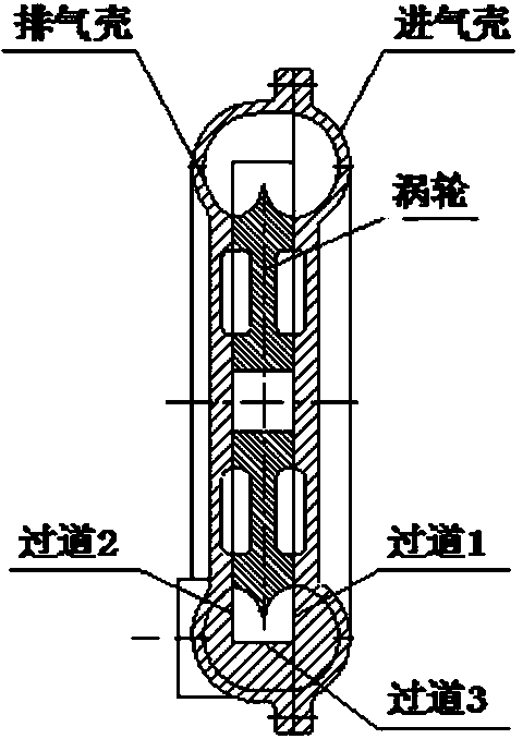
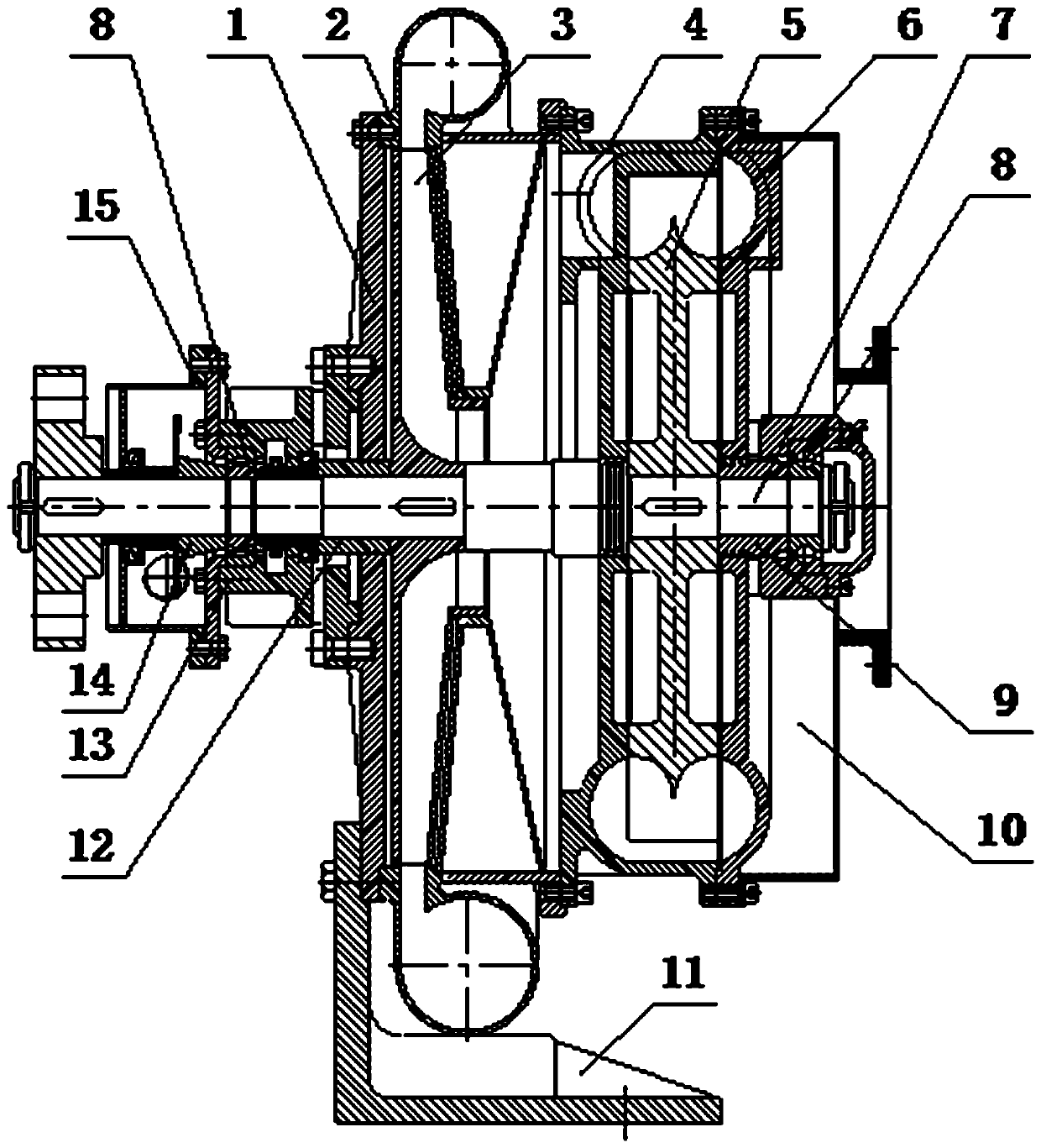
[0026] refer to figure 2 , the present embodiment provides a small high-pressure centrifugal blower, including a main shaft 7, an air intake shell 6, a turbine 5, an exhaust shell 4, a volute 2, an impeller 3, and a side cover 1; an air intake shell 6, a turbine 5, The exhaust casing 4, the volute 2, the impeller 3, and the side cover 1 are sequentially arranged on the main shaft 7, wherein the turbine 5 is located in a casing composed of the intake casing 6 and the exhaust casing 4, and the side walls of the turbine 5 and the casing are The movement gap is less than 0.5mm; the volute 2 is a high-velocity volute 2, which is used to convert the high-temperature gas from the exhaust case...


PUM


Abstract

The invention discloses a small-scale high-pressure centrifugal blower. The small-scale high-pressure centrifugal blower comprises a main shaft, a gas inlet housing, a turbine, an exhaust housing, a spiral housing, a vane wheel and a side cover, wherein the gas inlet housing, the turbine, the exhaust housing, the spiral housing, the vane wheel and the side cover are sequentially arranged on the main shaft; the turbine is located in a shell formed by the gas inlet housing and the exhaust housing, and the moving gap between the turbine and the side wall of the shell is smaller than 0.5mm; and the spiral housing is a high-flow velocity type spiral housing, and is used for converting high-temperature gas from the exhaust housing into a volute flow type high-pressure gas to be supplied to the vane wheel. According to the small-scale high-pressure centrifugal blower disclosed by the invention, part of the advantages of an annular blower are applied to the vane wheel and the spiral housing, so that the comprehensive performance of the small-scale high-pressure centrifugal blower is far better than that of a secondary annular blower having many defects, and the outlet pressure can achieve 60kPa; the design of the structure of the small-scale high-pressure centrifugal blower is adopted, so that the blower can be safely operated for a long time.

Description

technical field [0001] The invention relates to the technical field of centrifugal blowers, in particular to a small high-pressure centrifugal blower. Background technique [0002] The structure of the common annular blower on the market is as follows: Figure 1 As shown, it mainly includes intake casing, exhaust casing and worm gear. When the blower starts to work normally, there is a compression process in the casing. During this compression process, since the movement gap between aisles 1, 2, and 3 and the worm wheel is less than 0.5mm, the blades of the worm wheel rotating at high speed will bring part of the gas into the air. In aisles 1, 2, and 3, aisles 1, 2, and 3 will be subjected to countless high-temperature gas extrusions every time they are compressed. Extrusion causes expansion, which often causes worm wheel friction and blade breakage. In addition to the high mechanical failure rate, the overall quality of the annular blower is also poor, such as low outlet e...

Claims


Application Information

Patent Timeline
Patent Type & Authority Patents(China)
IPC IPC(8): F04D25/08F04D29/28F04D29/42F04D29/44F04D29/08F04D29/063F04D29/62
CPCF04D25/08F04D29/063F04D29/083F04D29/281F04D29/4233F04D29/441F04D29/626
Inventor 余广亢
Owner FUJIAN EAST ASIA BLOWER
Why Eureka
Try Eureka