Closed switch tube

A switch tube, closed technology, applied in the field of closed switch tube, to achieve smooth movement, reduce lateral impact force, and reduce frictional resistance

Active Publication Date: 2021-06-18
BEIJING JINGREN ELECTRICAL CO LTD +1
View PDF7 Cites 0 Cited by
  • Summary
  • Abstract
  • Description
  • Claims
  • Application Information

AI Technical Summary

Problems solved by technology

[0004] The above conventional closed switch tube is in a vacuum state, and the internal conductors are only in a normally closed state, which cannot meet some specific occasions. Therefore, the market needs a closed switch tube. It is normally open to meet different application occasions

Method used


Image

  • Closed switch tube
  • Closed switch tube
  • Closed switch tube

Examples


Embodiment Construction

[0023] Next, the technical solution in the present application will be described in conjunction with the drawings, and the reference will be described in the drawings in the drawings and detailed in the drawings and detailed in the following description. Examples and their various features and advantageous details. It should be noted that the features shown in the figures are not to be drawn according to scale. The present application has a description of known materials, components, and process techniques, so that the example embodiments of the present disclosure are not blurred. The examples given are intended to facilitate understanding of the practice of the examples of the present application, and further enable those skilled in the art. Thus, these examples should not be construed as limiting the scope of the embodiments of the present application.

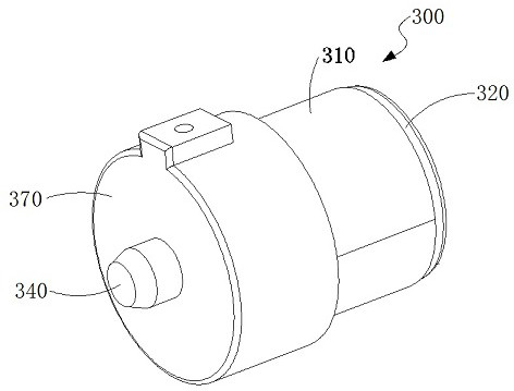
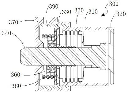
[0024] Such as figure 2 with image 3 As shown, the present embodiment discloses a closed switch tube 300 including an insulato...


PUM


Abstract

The invention discloses a closed switch tube, which comprises an insulator (310), a first conductor (320), a first support member (330), a second conductor (340) and a third conductor (370), and is characterized in that one end of the second conductor (340) is arranged in a cavity formed by the insulator (310), the first conductor (320) and the first support member (330) and can be in contact with or separated from the first conductor (320), the closed switch tube is characterized in that the third electric conductor (370) is arranged outside the insulator (310) in a sleeving mode and fixedly connected with the second electric conductor (340), and a second elastic piece (380) is arranged between the third electric conductor (370) and the first support member (330). According to the closed switch tube, under the condition that no external force is applied, the internal conductive pieces are at a normal open state, and different application occasions can be met.

Description

Technical field [0001] The present invention relates to the field of low-voltage electrical appliances, and is specifically a closed switch tube. Background technique [0002] In the high and low voltage distribution network, the high-break, explosion-proof places are particularly required, using vacuum switches to occupy an absolute advantage, the core components of the vacuum switch are closed switch tubes, or called a vacuum extinguishing room, which generally includes cover, ceramics , Bottom cover, moving contact, bellows composition. [0003] Such as figure 1 A closed switch tube structure shown in the prior art, the closed switch tube structure includes an upper cover 01, an insulator 02, a bellows 03, an movable contact 04, a bottom cover 05, and a static contact 06. The insulator 02 is provided between the casing 01 and the bottom cover 05, and the casing 01 is fixed to the insulator 02 and the bottom cover 05, respectively, and enclose a closed cavity, the bellows 03. T...

Claims


Application Information

Patent Timeline
Patent Type & Authority Applications(China)
IPC IPC(8): H01H33/664
CPCH01H33/664
Inventor 沈迪南寅王文涛任庆庆
Owner BEIJING JINGREN ELECTRICAL CO LTD
Why Eureka
Try Eureka