Eureka AIR delivers breakthrough ideas for toughest innovation challenges, trusted by R&D personnel around the world.

Optical module

An optical module and laser technology, applied in the field of optical communication, can solve the problems of relatively close distance, tight circuit board installation space, space occupied by shielding components, etc.

Active Publication Date: 2017-08-15
INNOLIGHT TECHNOLOGY (SUZHOU) LTD
View PDF6 Cites 16 Cited by
  • Summary
  • Abstract
  • Description
  • Claims
  • Application Information

AI Technical Summary

Problems solved by technology

[0004] In the prior art, since the light-receiving element and the light-emitting element are in the same space, and the distance is relatively close, the signal from the transmitting end is easily connected to the receiving end
In order to reduce crosstalk, shielding parts are usually used to separate them from the middle, so as to suppress the signal from being transmitted to the light-receiving element. However, in this way of setting shielding parts, the shielding parts occupy a certain amount of space, resulting in tight installation space on the circuit board in the housing. The problem

Method used


Image

  • Optical module
  • Optical module
  • Optical module

Examples


Embodiment Construction

[0024] The application will be described in detail below in conjunction with specific implementations shown in the accompanying drawings. However, these implementations do not limit the present application, and any structural, method, or functional changes made by those skilled in the art based on these implementations are included in the protection scope of the present application.

[0025] In each drawing of the present application, some dimensions of structures or parts are exaggerated relative to other structures or parts for the convenience of illustration, and therefore, are only used to illustrate the basic structure of the subject matter of the present application.

[0026] The terms used herein to denote relative spatial positions such as "upper", "above", "under", "under", etc. are for convenience of description to describe the relative position of one element or feature relative to another as shown in the drawings. Relationships of units or features. The terms of s...


PUM


Abstract

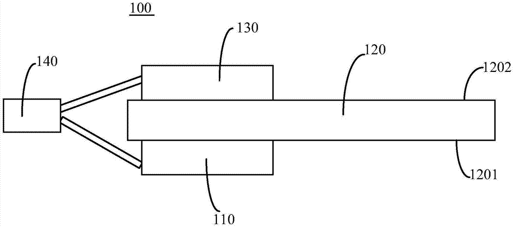
The present invention discloses an optical module. The optical module includes a printed circuit board, a light emitting element, a light receiving element and an optic fiber port corresponding to the light emitting element and the light receiving element; the printed circuit board comprises a first surface and a second surface which are arranged oppositely; the light receiving element is mounted on the second surface of the printed circuit board; and the light emitting element is mounted on the first surface of the printed circuit board or is adjacent to an end surface of the printed circuit board. According to the optical module of the invention, the light emitting element and the light receiving element are arranged at the two sides of the printed circuit board, and therefore, the signal crosstalk of the light-emitting element and the light-receiving element can be effectively reduced, and the performance of the optical module can be improved; and a shielding component is not required, and therefore, the problem of space occupation caused by the shielding component can be avoided.

Description

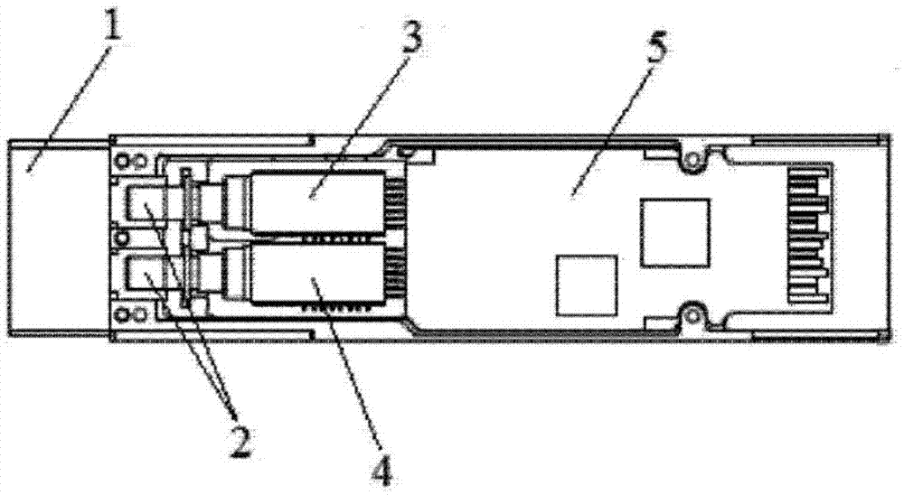
technical field [0001] The present application belongs to the technical field of optical communication, and in particular relates to an optical module. Background technique [0002] The optical module is composed of optoelectronic devices, functional circuits and optical ports. Among them, optoelectronic devices include two parts: emission and reception. To put it simply, the main function of the optical module is to realize photoelectric conversion. At the sending end, the electrical signal is converted into an optical signal. After transmission through the optical fiber, the optical signal is converted into an electrical signal at the receiving end, thereby realizing the transmission of information. [0003] Currently commonly used optical modules use the light-emitting element and the light-receiving element to be contained in the same plane space. figure 1 The structure of the QSFP+ optical module in the prior art is shown as an example. The QSFP+ optical module includ...

Claims


Application Information

Patent Timeline
IPC IPC(8): G02B6/42
CPCG02B6/4201G02B6/428G02B6/4245
Inventor 陈龙孙雨舟王冬寒李伟龙于登群
Owner INNOLIGHT TECHNOLOGY (SUZHOU) LTD
Why Eureka
Eureka Blog
Learn More