Connecting structure and grass trimmer head device

A connection structure and the technology of mowing heads, which are applied in the direction of cutters, agricultural machinery and implements, etc., can solve the problems of short service life of the mowing head and easy vibration of the mowing head

Inactive Publication Date: 2017-08-18
ZHEJIANG TITAN MACHINERY
View PDF6 Cites 2 Cited by
  • Summary
  • Abstract
  • Description
  • Claims
  • Application Information

AI Technical Summary

Problems solved by technology

[0004] Among the various components of the mowing machine, the mowing head is the main working part, and the mowing head is provided with a mowing rope. The mowing rope is the main structural part for mowing grass. The mowing head fix...

Method used


Image

  • Connecting structure and grass trimmer head device
  • Connecting structure and grass trimmer head device
  • Connecting structure and grass trimmer head device

Examples


Embodiment 1

[0036] The specific implementation of this embodiment is as follows:

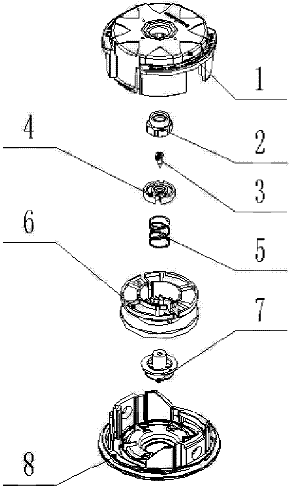
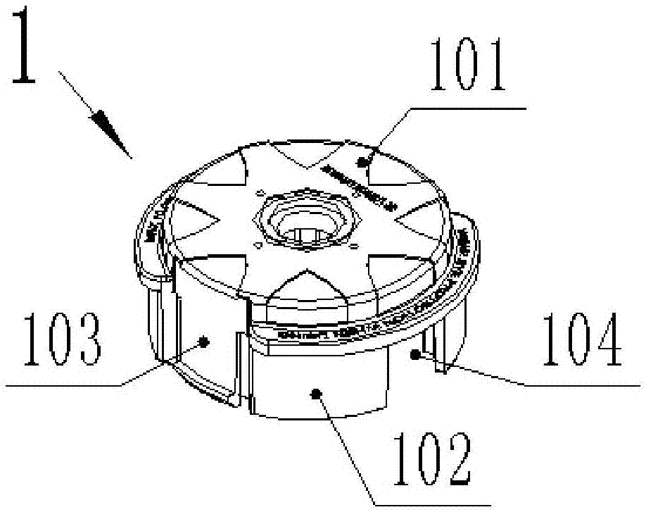
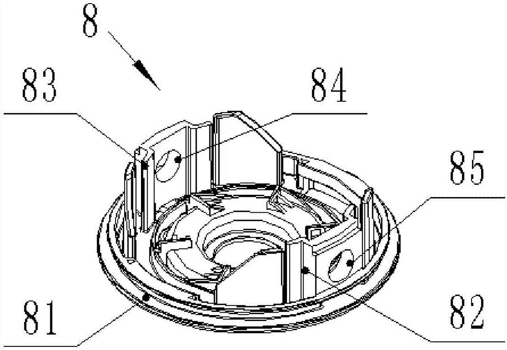
[0037] Such as figure 1 As shown in -3, this embodiment provides a connection structure, including a sheave box 1 and a large cover 8 that are interlocked from top to bottom, and a small cover 4 is also provided between the sheave box 1 and the big cover 8, and the small cover 4 A sheave 6 and a connecting block 7 are arranged between the big cover 8, a left-handed nut 2 is arranged between the small cover 4 and the sheave box 1, and the left-handed nut 2 is pressed on the sheave box 1, and the left-handed nut 2 and the sheave The box 1 has an interference fit; it also includes a rotary compression spring 5 and a self-tapping screw 3, the rotary compression spring 5 is set at the center of the sheave 6, the rotary compression spring 5 is sleeved on the raised structure of the connecting block 7, and the self-tapping screw 3 Through the small cover 4, the rotating compression spring 5 and the protrusion str...

Embodiment 2

[0049] Such as figure 1 As shown in -4, a grass trimming device provided by this embodiment includes the connection structure of the first embodiment above, a through hole is provided in the radial direction of the large cover 8, and a grass trimming rope 13 and two outlet ropes are also included. Clip 12, the rope-out clip 12 is respectively arranged on the outside of the through hole of the big cover 8, and the grass rope 13 passes through the rope clip 12, the big cover 8 and the rope clip 12 successively, and the grass rope 13 is arranged on the The bottom of the connecting block 7; the bottom of the connecting block 7 is also provided with an impact compression spring 9, a compression reed 10 and an impact head 11 from top to bottom, and the impact head 11 is locked with the bottom of the big cover 8, and the connection block 7 can Under the effect of stage clip 9, on the axial direction of big cover 8, bounce up and down vertically.

[0050] Specifically, the upper part...


PUM


Abstract

The invention provides a connecting structure and a grass trimmer head device, and relates to the field of garden equipment. The connecting structure comprises a rope wheel box and a big cover which are mutually buckled from top to bottom, a small cover is arranged between the rope wheel box and the big cover, a rope wheel and a connecting block are arranged between the small cover and the big cover, a left-handed nut is arranged between the small cover and the rope wheel box and pressed and mounted on the rope wheel box, and the left-handed nut is in interference fit with the rope wheel box; the connecting structure further comprises a rotating compression spring and a self-tapping screw, the rotating compression spring is arranged in the center of the rope wheel and connected to a protruding structure of the connecting block in a sleeving mode, the self-tapping screw penetrates through the small cover, and the rotating compression spring is in thread connection with the protruding structure of the connecting block. The invention further relates to the grass trimmer head device which comprises the connecting structure, a grass trimmer rope, two rope outlet clamping pieces, an impact compression spring, a leaf spring and an impact head. According to the technical scheme, the big cover and the rope wheel box can be stably buckled, and the service life of a grass trimmer head is prolonged.

Description

technical field [0001] The invention relates to the technical field of garden equipment, in particular to a connection structure and a grass cutting head device. Background technique [0002] Grass trimmers, all hand-held tools for cutting weeds in lawns, gardens, pastures, etc. According to the power source, it can be divided into oil-driven and electric; according to the structure of the power head, it can be divided into front-mounted power and rear-mounted power; Agricultural livestock machinery for pasture. [0003] The working principle of the lawn trimmer is mainly that the motor is used as the supporting power to transmit the power to the main shaft, and the gear at the other end of the main shaft transmits the speed-adjusted power to the grass kun through the gear box, universal joint, etc. When the material to be processed When it enters between the upper and lower pressing grass kuns, it is clamped by the pressing Cao Kun and sent to the guillotine cutting mecha...

Claims


Application Information

Patent Timeline
IPC IPC(8): A01D34/416
CPCA01D34/4165
Inventor 郭晓峰
Owner ZHEJIANG TITAN MACHINERY
Why Eureka
Try Eureka