Positive-pressure slow release joint

A slow-release, positive-pressure cavity technology, applied in the field of medical machinery, can solve problems such as inconvenient use for medical staff, inability to form positive pressure in time, and affect medical effects, so as to reduce blood backflow, prevent thrombus formation, and reduce work volume effect

Active Publication Date: 2017-08-18
广东先来医疗器械有限公司
View PDF11 Cites 9 Cited by
  • Summary
  • Abstract
  • Description
  • Claims
  • Application Information

AI Technical Summary

Problems solved by technology

During use, before the continuous positive pressure liquid supply device is installed on the three-way joint, the medical staff operate the continuous positive pressure liquid supply device to inhale the liquid, and then install the continuous positive pressure liquid supply device on the three-way joint to achieve continuous positive pressure. The liquid inside the pressure liquid supply device leaks out to the output port of the three-way joint under positive pressure, so as to prevent the formation of thrombus. After that, the positive pressure cannot be formed in the tee joint in time, causing blood backflow and affecting the medical effect

Method used


Image

  • Positive-pressure slow release joint
  • Positive-pressure slow release joint
  • Positive-pressure slow release joint

Examples


Embodiment Construction

[0039] The present invention will be described in detail below in conjunction with specific embodiments and accompanying drawings.

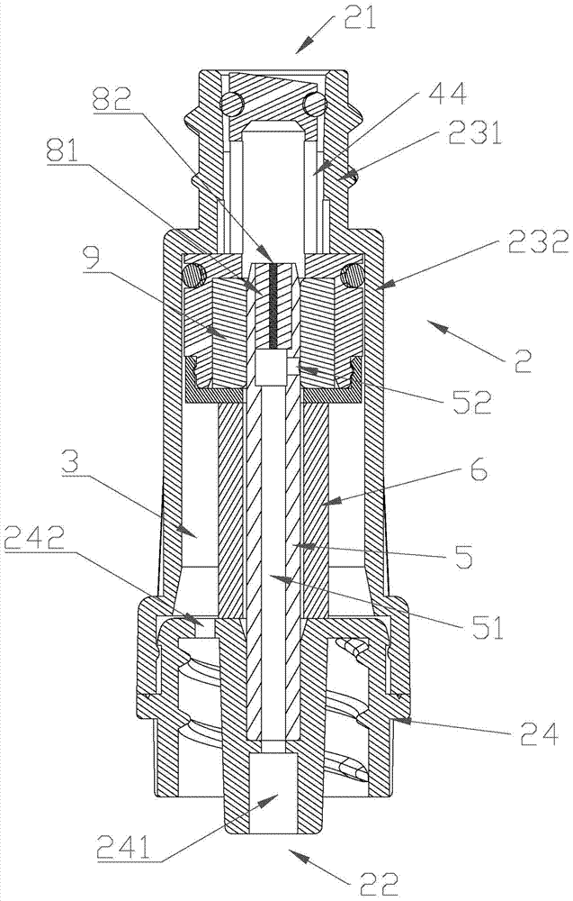
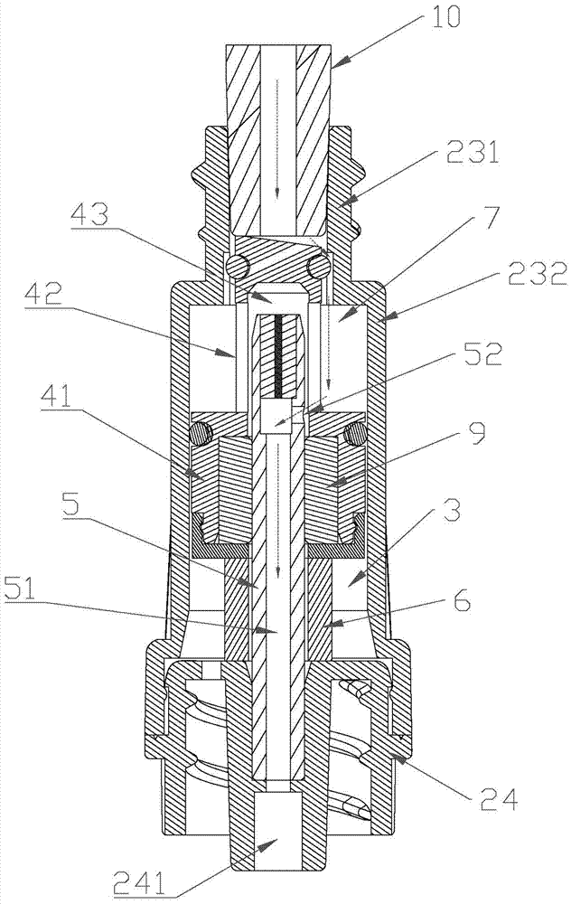
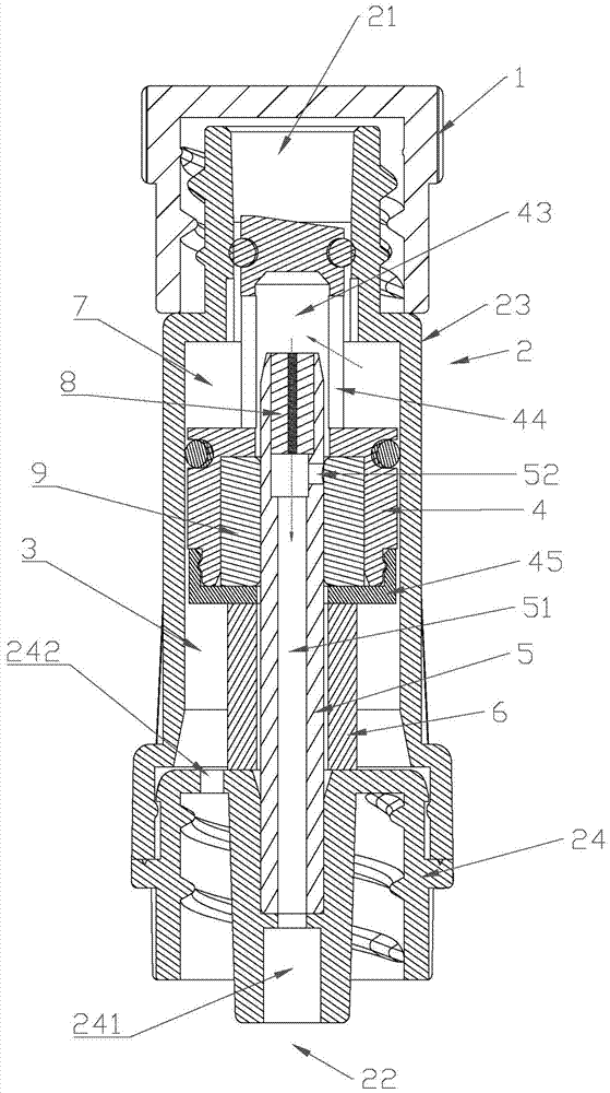
[0040] A kind of positive pressure slow-release joint of this embodiment, such as Figure 1 to Figure 5 As shown, it includes a hollow shell 2, a protective cap 1 and a piston 4 arranged inside the shell 2. The piston 4 can slide in the shell 2. The upper end of the shell 2 is an input port 21, and the lower end of the shell 2 is an output port 22. The cap 1 and the input port 21 are threadedly connected to cover the input port 21 . The shell 2 includes a shell body 23 and a lower connecting seat 24 which are fixedly connected to each other. The shell body 23 includes a sealing section 231 and a movable section 232 arranged up and down in sequence. The diameter of the sealing section 231 is smaller than that of the movable section 232 . The lower connecting seat 24 is provided with an output hole 241 for communicating with an external indwelling...


PUM


Abstract

The invention discloses a positive-pressure slow release joint. In use, an external infusion set is inserted into a sealed section, a piston is pushed to move downwards till the piston retreats to an active section, an external joint communicates with a positive-pressure chamber, and liquid in the external infusion set sequentially passes an input port, the sealed section, a diversion channel, the positive-pressure chamber, a liquid passing hole, a column channel and an output port. When infusion is completed, the external joint is pulled out to stop infusion, the piston is driven by an elastic part to block the positive-pressure chamber again, and at the same time, the liquid passing hole is also blocked by the piston; at the moment, the positive-pressure chamber is filled with liquid, and a micro-infiltration channel is formed in the joint, so that formation of thrombi when a venous indwelling needle stops infusion can be effectively prevented. Normal infusion can be realized, micro-infiltration can be formed in the joint when infusion is stopped, and thrombosis can be effectively prevented; furthermore, after the external infusion set is removed, the joint is automatically switched to the positive-pressure micro-infiltration state, so that blood return is reduced, additional operation of medical staff is not needed, and working intensity of medical staff is reduced greatly.

Description

technical field [0001] The invention relates to the technical field of medical machinery, in particular to a positive pressure slow release joint. Background technique [0002] With the continuous improvement of nursing technology and the continuous update of medical supplies, the indwelling needle has been recommended by the World Health Organization as the safest puncture tool. It is easy to operate, can reduce repeated punctures, protect blood vessels, relieve pain of patients, facilitate clinical medication and emergency rescue, and reduce the workload of nurses. It has been widely used in clinical practice. However, some new problems have appeared in the clinical work of intravenous indwelling needles. After each infusion, if the needle tube or the cone or the external connector of the infusion set are pulled out directly from the indwelling device, a cavity will be formed, resulting in negative pressure. , causing blood backflow into the indwelling device, forming thr...

Claims


Application Information

Patent Timeline
Patent Type & Authority Applications(China)
IPC IPC(8): A61M5/14A61M39/10A61M39/02
CPCA61M5/14A61M39/0208A61M39/10A61M2039/0205
Inventor 陈达锦李林风陈志强
Owner 广东先来医疗器械有限公司
Why Eureka
Try Eureka