speed skates
A technology for skating shoes and skates, which is applied to skates, skating parts, sports accessories, etc., can solve problems such as unreliable lubrication effect, and achieve the effects of solving uneven ice surface, improving lubrication effect, and increasing sliding speed.
- Summary
- Abstract
- Description
- Claims
- Application Information
AI Technical Summary
Problems solved by technology
Method used
Image
Examples
specific Embodiment approach 1
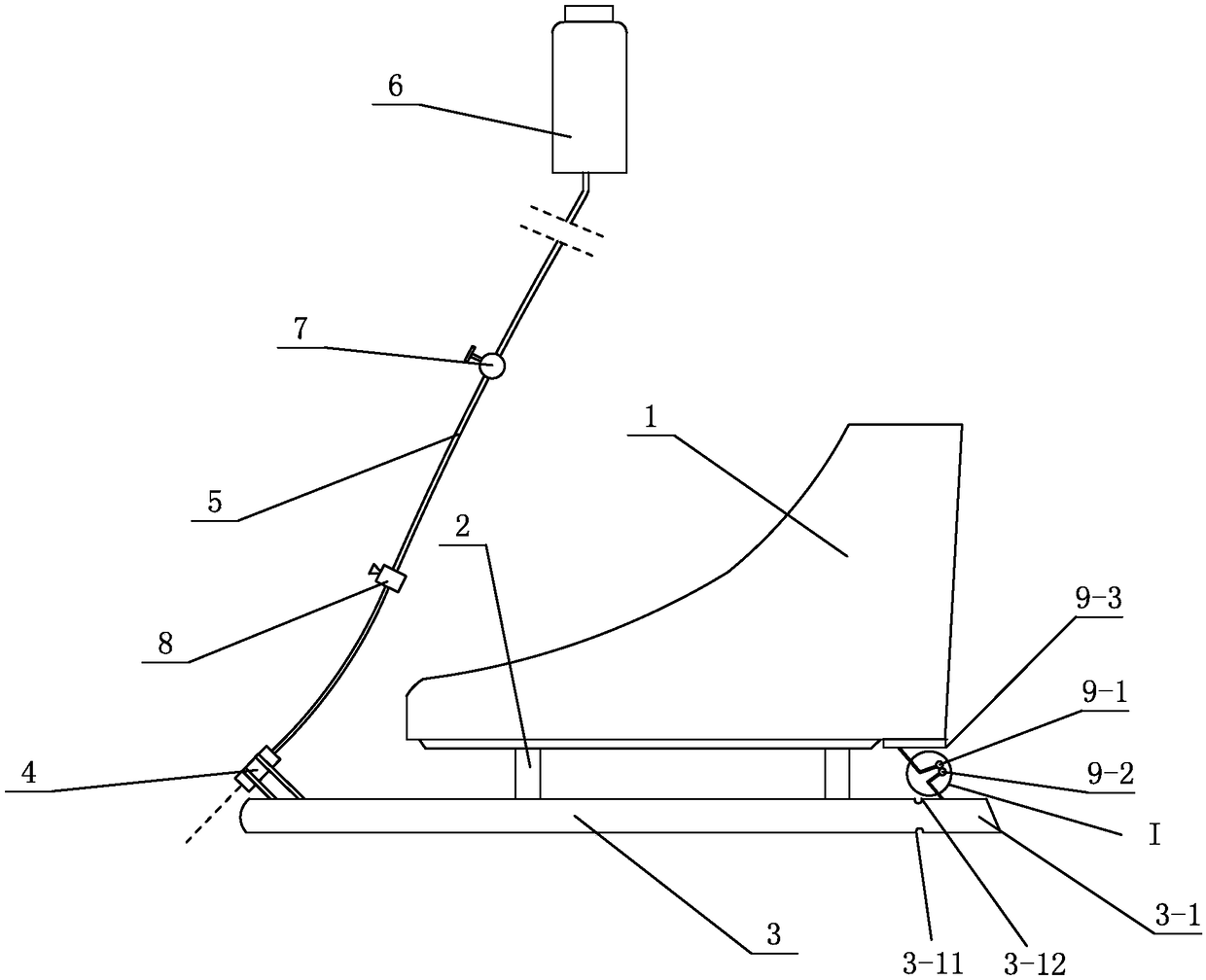
[0009] Specific implementation mode one: combine figure 1 This embodiment will be described. The present embodiment speed skating skate comprises shoe body 1, connecting frame 2 and cutter body 3, and cutter body 3 is fixed on the bottom surface of shoe body 1 by connecting frame 2, and it also includes nozzle 4, connecting pipe 5, water storage tank 6 and Manual switch 7, nozzle 4 is fixed on the upper surface of the front end of cutter body 3, the nozzle of nozzle 4 points to the place 1.5 to 5.5 mm ahead of the front end of cutter body 3, and the water inlet of nozzle 4 is connected to the water storage tank 6 through connecting pipe 5. On the water outlet, the connecting pipe 5 is provided with a manual switch 7 . When the speed skater is skating, the water storage tank 6 is suspended on the waist, and only connected to the shower nozzle 4 by a soft connecting pipe 5 . Shower nozzle 4, connecting pipe 5 and water storage tank 6 all can be selected non-metallic material f...
specific Embodiment approach 2
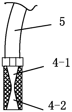
[0010] Specific implementation mode two: combination figure 2 Describe this embodiment, the difference between this embodiment and Embodiment 1 is: the inner cavity of the nozzle 4 is divided into a contraction beam section 4-1 and an expansion beam section 4-2 along its length direction, and the water The fluid flows through the constricted beam section 4-1 and the expanded beam section 4-2 successively, and the constricted beam section 4-1 and the expanded beam section 4-2 are tapered inner holes. With such an arrangement, when the fluid moves in the constricted beam section 4-1, the fluid is continuously accelerated according to the principle that the flow velocity is small at a large cross-section and high at a small cross-section. When reaching the narrow throat, the flow velocity reaches a certain scale. After crossing the narrow throat, it is just according to the principle that the larger the cross-section, the faster the flow velocity, so it can be sprayed at a high...
specific Embodiment approach 3
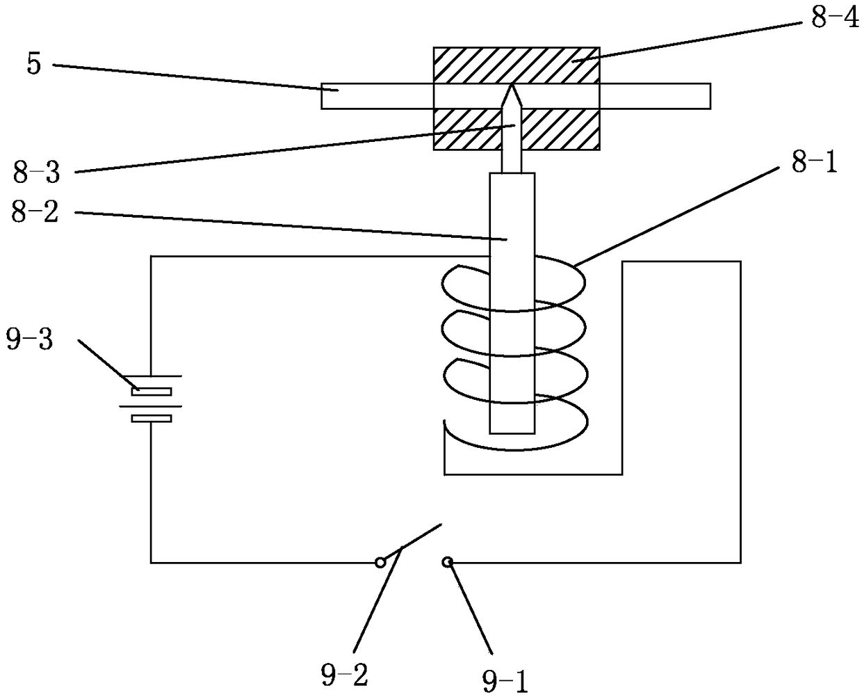
[0012] Specific implementation mode three: combination figure 1 , image 3 with Figure 4 Describe this embodiment. The difference between this embodiment and Embodiment 1 is that it also includes an electromagnetic pipeline valve 8 and a control circuit. The electromagnetic pipeline valve 8 is composed of an electromagnetic coil 8-1, an armature 8-2, a valve core 8- 3 and valve body 8-4, the control circuit is composed of static contact 9-1, moving contact 9-2 and battery 9-3, and the electromagnetic pipeline valve 8 is set on the connecting pipe 5 to control the flow of water The spool 8-3 is set in the valve body 8-4, the front end of the armature 8-2 is fixed with the spool 8-3, the rear end of the armature 8-2 is set in the electromagnetic coil 8-1, and the battery 9- The positive pole of 3 connects one end of electromagnetic coil 8-1, and the other end of electromagnetic coil 8-1 connects static contact 9-1, and movable contact 9-2 connects the negative pole of battery...
PUM
 Abstract
Description
Claims
Application Information
 - R&D
- Intellectual Property
- Life Sciences
- Materials
- Tech Scout
- Unparalleled Data Quality
- Higher Quality Content
- 60% Fewer Hallucinations
Browse by: Latest US Patents, China's latest patents, Technical Efficacy Thesaurus, Application Domain, Technology Topic, Popular Technical Reports.
© 2025 PatSnap. All rights reserved.Legal|Privacy policy|Modern Slavery Act Transparency Statement|Sitemap|About US| Contact US: help@patsnap.com


