Pouring equipment and bottom pouring furnace thereof

A bottom pouring and sprue technology, which is applied in casting equipment, metal processing equipment, and equipment that sends molten metal into molds, etc., can solve the problem of inability to meet the requirements of small flow pouring quality, high precision and high purity processing Production requirements, inability to accurately control pouring flow, etc.

Pending Publication Date: 2017-08-18
QINGDAO YUNLU ADVANCED MATERIALS TECH CO LTD
View PDF0 Cites 2 Cited by
  • Summary
  • Abstract
  • Description
  • Claims
  • Application Information

AI Technical Summary

Problems solved by technology

[0003] The current pouring method usually consists of two types. One is pouring at the sprue on the upper part of the furnace body. This method cannot accurately control the pouring flow, and it is very easy to pour the oxides on the top of the furnace directly into the downstream equipment during the operation, which cannot meet the high precision requirements. and high-purity processing and production requirements; the other is ladle pouring, which is widely used in the metallurgical industry. This pouring method can quickly complete a large number of pouring operations in a short period of time, but it cannot meet small flow and long-term pouring operations. Requirements for pouring quality in the process

Method used


Image

  • Pouring equipment and bottom pouring furnace thereof

Examples


Embodiment Construction

[0020] The core of the present invention is to provide a bottom pouring furnace, which can effectively improve the operation effect of small flow pouring and ensure its pouring quality; meanwhile, it provides a pouring equipment using the above bottom pouring furnace.

[0021] In order to enable those skilled in the art to better understand the solution of the present invention, the present invention will be further described in detail below in conjunction with the accompanying drawings and specific embodiments.

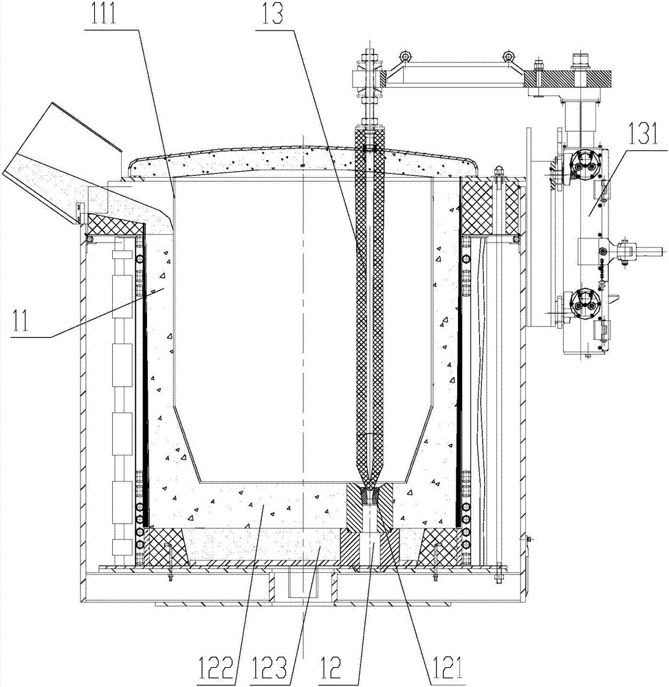
[0022] Please refer to figure 1 , figure 1 It is a schematic diagram of the cooperative structure of the bottom injection furnace and the cooling roll provided by a specific embodiment of the present invention.

[0023] In a specific embodiment, the bottom injection furnace provided by the present invention includes a furnace body 11, a furnace seat is provided at the bottom of the furnace body 11, and a pouring port 12 is vertically penetrated on the furnace seat, ...


PUM

PropertyMeasurementUnit
Diameteraaaaaaaaaa

Abstract

The invention discloses a bottom pouring furnace which comprises a furnace body. A furnace base is arranged at the bottom of the furnace body. A sprue gate penetrates through the furnace base in the vertical direction. A plug rod is arranged inside the furnace body. The bottom end of the plug rod aligns the sprue gate to be matched, and the diameter of the plug rod is larger than that of the sprue gate. The furnace body is provided with a driving device capable of driving the plug rod to move in the vertical direction. By the adoption of the bottom pouring furnace, the small-flow pouring operation effect can be effectively improved, and the pouring quality is guaranteed. The invention further discloses pouring equipment using the bottom pouring furnace.

Description

technical field [0001] The invention relates to the technical field of supporting components of pouring equipment, in particular to a bottom pouring furnace. The invention also relates to a pouring equipment using the bottom pouring furnace. Background technique [0002] In the existing industrial fields involving molten metal pouring such as amorphous strips and steel rolling, generally larger pouring equipment is the mainstream equipment, but there is no targeted equipment for some production operations with small pouring volumes. Pouring equipment support. [0003] The current pouring method usually consists of two types. One is pouring at the sprue on the upper part of the furnace body. This method cannot accurately control the pouring flow, and it is very easy to pour the oxides on the top of the furnace directly into the downstream equipment during the operation, which cannot meet the high precision requirements. and high-purity processing and production requirements...

Claims


Application Information

Patent Timeline
IPC IPC(8): B22D35/04
CPCB22D35/04
Inventor 李晓雨庞靖刘树海李庆华
Owner QINGDAO YUNLU ADVANCED MATERIALS TECH CO LTD
Why Eureka
Try Eureka