Constant-temperature structure for belt transmission main shafts

A technology of belt transmission and transmission spindle, which is applied in the direction of driving devices, metal processing machinery parts, maintenance and safety accessories, etc., which can solve the problems of deterioration of machining accuracy of machine tools, temperature rise of transmission parts, and large temperature rise, so as to improve precision The effect of stabilizing performance

Inactive Publication Date: 2017-08-18
NANTONG GUOSHENG INTELLIGENCE TECH GRP CO LTD
View PDF4 Cites 0 Cited by
  • Summary
  • Abstract
  • Description
  • Claims
  • Application Information

AI Technical Summary

Problems solved by technology

[0002] The power transmission of the spindle of CNC machine tools generally adopts a pulley belt transmission structure. This structure has the characteristics of convenient installation and small impact of abnormal transmission impact. However, the heat generated by the friction between the belt and the pulley and the force deformation will cause the temperature of the transmission parts to rise rapidly. , due to the temperature rise, the main shaft and other transmission parts are deformed. Through actual measurement, we found that the temperature change of the main transmission box at 2000 rpm within 30 minutes can reach 10 ℃
[0003] The deformation of the main shaft caused by the change of temperature difference reaches 0.04mm, and the temperature rise speed is faster when the main shaft of the machine tool is cutting, and the temperature rise is larger. Produce defective products

Method used


Image

  • Constant-temperature structure for belt transmission main shafts
  • Constant-temperature structure for belt transmission main shafts
  • Constant-temperature structure for belt transmission main shafts

Examples


Embodiment

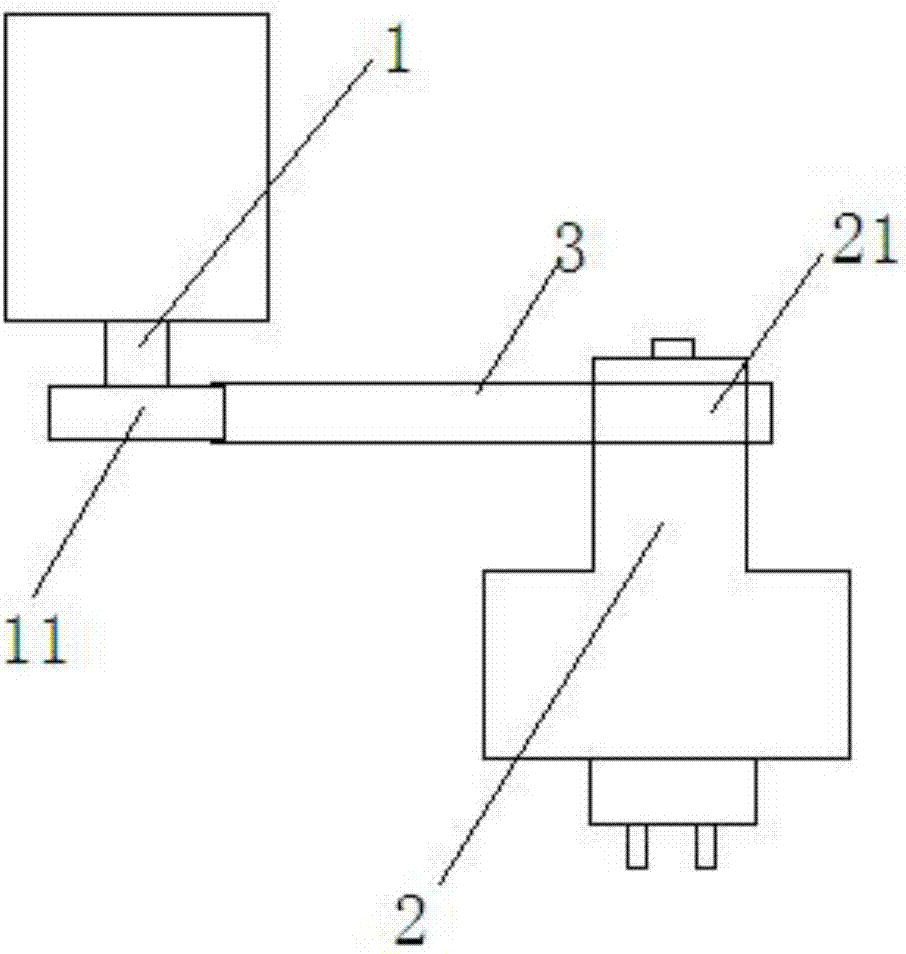
[0014] Such as figure 1 As shown, the existing CNC machine tool spindle power transmission adopts a pulley belt transmission structure. This structure has the characteristics of convenient installation and small impact on transmission abnormalities. The heat generated by the deformation will cause the temperature of the transmission parts to rise rapidly. Due to the temperature rise, the transmission parts such as the spindle will be deformed and lose their own precision.

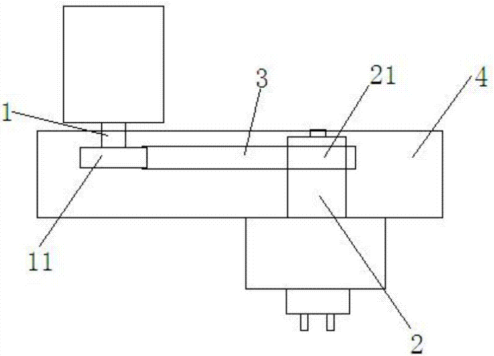
[0015] In order to ensure the stable accuracy of the machine tool and reduce the accuracy change of the main shaft due to thermal deformation, the structure of the transmission part is modified, as follows: Figure 2-3 As shown, a constant temperature structure of a belt drive main shaft includes a first transmission main shaft 1, a second transmission main shaft 2, a belt 3, a casing 4, a first pulley 11 and a second pulley 21; A first pulley 11 is installed, and a second pulley 21 is installed on the sec...


PUM


Abstract

The invention discloses a constant-temperature structure for belt transmission main shafts. The constant-temperature structure for the belt transmission main shafts comprises the first transmission main shaft, the second transmission main shaft, a belt, a box body, a first belt wheel and a second belt wheel, wherein the first belt wheel is mounted on the first transmission main shaft, the second belt wheel is mounted on the second transmission main shaft, the first belt wheel and the second belt wheel are in transmission connection through the belt, and the first belt wheel, the second belt wheel and the belt are all located in the box body; and in the belt transmission process, air is continuously injected into the box body through a fan via an air inlet, the air rapidly moves to an exhaust port in the belt transmission direction, an exhaust fan is connected to the outer side of an exhaust box so as to pump out air in the box body, and heat generated in the belt transmission process is taken away at the same time. According to the constant-temperature structure for the belt transmission main shafts, the box body is additionally arranged on the belt transmission part, and air is injected into the box body and pumped away through exhausting, so that heat generated in the belt transmission process is taken away, the influence of temperature rise on the main shafts is reduced, and the precision stability of the main shafts is improved.

Description

technical field [0001] The invention belongs to the field of mechanical manufacturing, and in particular relates to a constant temperature structure of a belt drive main shaft. Background technique [0002] The power transmission of the spindle of CNC machine tools generally adopts a pulley belt transmission structure. This structure has the characteristics of convenient installation and small impact of abnormal transmission impact. However, the heat generated by the friction between the belt and the pulley and the force deformation will cause the temperature of the transmission parts to rise rapidly. , Due to the temperature rise, the main shaft and other transmission parts are deformed. Through actual measurement, we found that the temperature change of the main transmission box reaches 10°C under the condition of 2000 rpm within 30 minutes. [0003] The deformation of the spindle caused by the change of temperature difference reaches 0.04mm, and the temperature rise speed...

Claims


Application Information

Patent Timeline
Patent Type & Authority Applications(China)
IPC IPC(8): B23Q5/04B23Q11/12
CPCB23Q5/043B23Q11/127
Inventor 刘传进潘卫国任东崔德友徐新朋缪申刘志华
Owner NANTONG GUOSHENG INTELLIGENCE TECH GRP CO LTD
Why Eureka
Try Eureka