Deformation polishing disc based on piezoelectric ceramic drivers

A piezoelectric ceramic and drive technology, applied in the field of aspheric mirror polishing equipment, can solve the problems of poor stability of the polishing disc and small diameter-thickness ratio of the polishing disc, and achieve the effects of compact structure, low cost and extended service life

Pending Publication Date: 2017-08-18
LASER FUSION RES CENT CHINA ACAD OF ENG PHYSICS
View PDF0 Cites 2 Cited by
  • Summary
  • Abstract
  • Description
  • Claims
  • Application Information

AI Technical Summary

Problems solved by technology

Since the expansion and contraction of the piezoelectric ceramic driver is proportional to its own length, which is about one-thousandth of the length, in order to ensure the deformation of the polishing disc, the length of the selected piezoelectric ceramic driver should not be too short, which will make the diameter of the polishing disc thicker. Ratio is very small, resulting in poor stability of the polishing disc

Method used


Image

  • Deformation polishing disc based on piezoelectric ceramic drivers
  • Deformation polishing disc based on piezoelectric ceramic drivers
  • Deformation polishing disc based on piezoelectric ceramic drivers

Examples


Embodiment 1

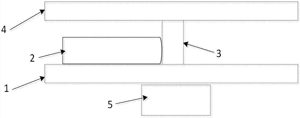
[0030] like figure 1 As shown, a deformed polishing disc based on piezoelectric ceramic drivers includes a base 1, a piezoelectric ceramic driver 2, an elastic sheet 3 and a base plate 4, that is to say, the elastic sheet 3 and the piezoelectric ceramic driver 2 One-to-one arrangement, the piezoelectric ceramic driver 2 is located on the upper surface of the base 1, the substrate 4 is located above the piezoelectric ceramic driver 2, the lower surface of the base 1 is provided with a conductive slip ring 5, and the piezoelectric ceramic The driver 2 is connected to a voltage source through a conductive slip ring 5, and the base plate 4 is an aluminum spherical thin plate.

[0031] The elastic piece 3 is installed on the upper surface of the base 1 along its radial direction, and in order to increase the diameter-thickness ratio of the polishing disc, the piezoelectric ceramic driver 2 is installed on the upper surface of the base 1 along its axial direction, and one end thereo...

Embodiment 2

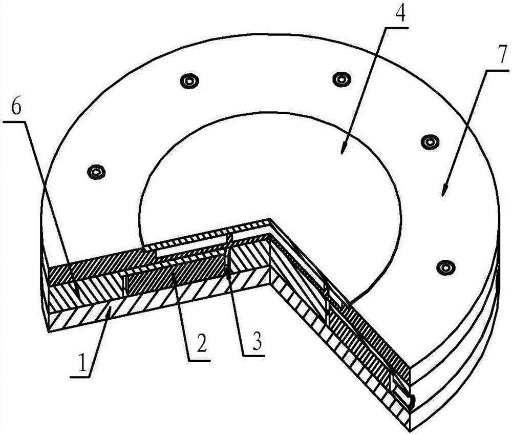
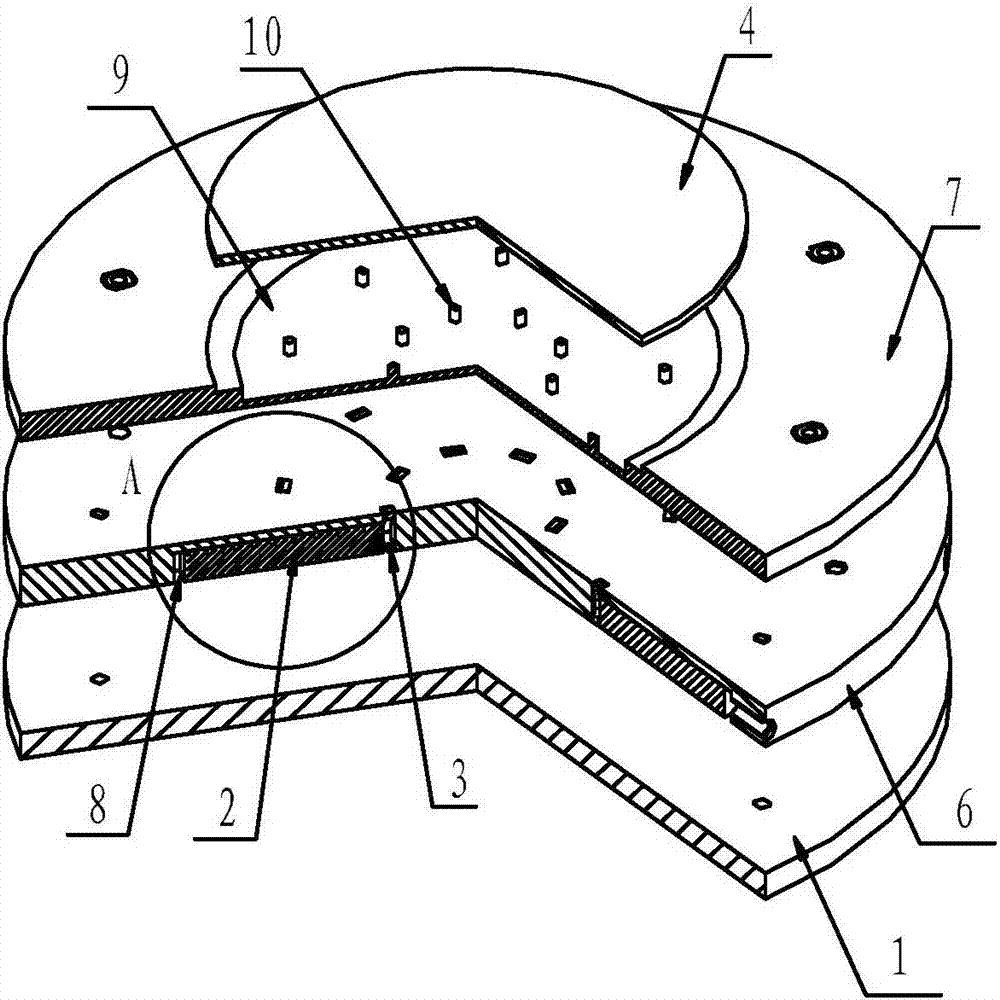
[0037] like Figure 2-4 As shown, the same parts of this embodiment and Embodiment 1 will not be repeated, and the difference is:

[0038]A fixed disc 6 is provided between the base 1 and the base plate 4 for installing the piezoelectric ceramic driver 2 and the elastic sheet 3. A long groove 8 is provided in the fixed disc 6, and the piezoelectric ceramic driver 2, elastic The pieces 3 are all located in the elongated groove 8 , and the clamping member is located at the edge of the fixed disk 6 and abuts against the end of the piezoelectric ceramic driver 2 .

[0039] Above the piezoelectric ceramic driver 2 is provided a support plate 7 of aluminum structure or steel structure, a groove 9 is provided in the support plate 7, the base plate 4 is located in the groove 9, and the upper surface of the base plate 4 Higher than the upper surface of the support plate 7, it is convenient for the base plate 4 to polish the aspheric mirror. The corresponding elastic sheet 3 is provide...


PUM

PropertyMeasurementUnit
thicknessaaaaaaaaaa
lengthaaaaaaaaaa

Abstract

The invention relates to a deformation polishing disk based on a piezoelectric ceramic driver, which belongs to the technical field of aspheric mirror polishing equipment, and includes a base, a plurality of piezoelectric ceramic drivers on the base and a base plate located above the piezoelectric ceramic driver, and multiple An elastic piece, the elastic piece is installed on the upper surface of the base along its radial direction, and it is arranged one-to-one with the piezoelectric ceramic driver, and the piezoelectric ceramic driver is installed on the upper surface of the base along its axial direction, and one end of it points to In the center of the base, the elastic piece is opposed to the end of the piezoelectric ceramic driver pointing to the center of the base. After the piezoelectric ceramic driver exerts a pressing force on the elastic piece, the elastic piece will expand and contract along its axial direction to change the surface of the base plate. Shape, the invention increases the diameter-thickness ratio of the polishing disc, has a compact structure, significantly improves the stability of the polishing disc during rotation and the compatibility with the workpiece, has low cost, and helps to prolong the service life of the piezoelectric ceramic driver.

Description

technical field [0001] The invention belongs to the technical field of aspheric mirror polishing equipment, and in particular relates to a deformation polishing disk based on a piezoelectric ceramic driver. Background technique [0002] In recent years, people have developed a computer-controlled deformable polishing disc technology for polishing aspheric mirrors. During the polishing process, people can automatically change the shape of the polishing disc at any time to adapt to the shape of the mirror surface wherever it goes. At present, active polishing disc technology is mainly divided into two categories: [0003] One is the active grinding disc technology based on the bending moment driver. Multiple groups of bending moment drivers are evenly distributed on the back of the polishing disc, and different bending moments are applied to the polishing disc, thereby changing the curvature of the polishing disc and deforming the polishing disc to ensure any Match the workp...

Claims


Application Information

Patent Timeline
Patent Type & Authority Applications(China)
IPC IPC(8): B24B13/01B24B13/02
CPCB24B13/012B24B13/02
Inventor 代万俊杨英薛峤陈良明胡东霞袁强张鑫王德恩赵军普张晓璐曾发王深圳张崑周维朱启华郑奎兴粟敬钦
Owner LASER FUSION RES CENT CHINA ACAD OF ENG PHYSICS
Why Eureka
Try Eureka