Radiation heating and temperature measuring device for phase transition process of translucent materials with low melting point
A translucent material and radiation heating technology, applied in the field of materials, to achieve the effect of continuous adjustment of radiation power, stable radiation heat flux density, and convenient change
- Summary
- Abstract
- Description
- Claims
- Application Information
AI Technical Summary
Problems solved by technology
Method used
Image
Examples
specific Embodiment approach 1
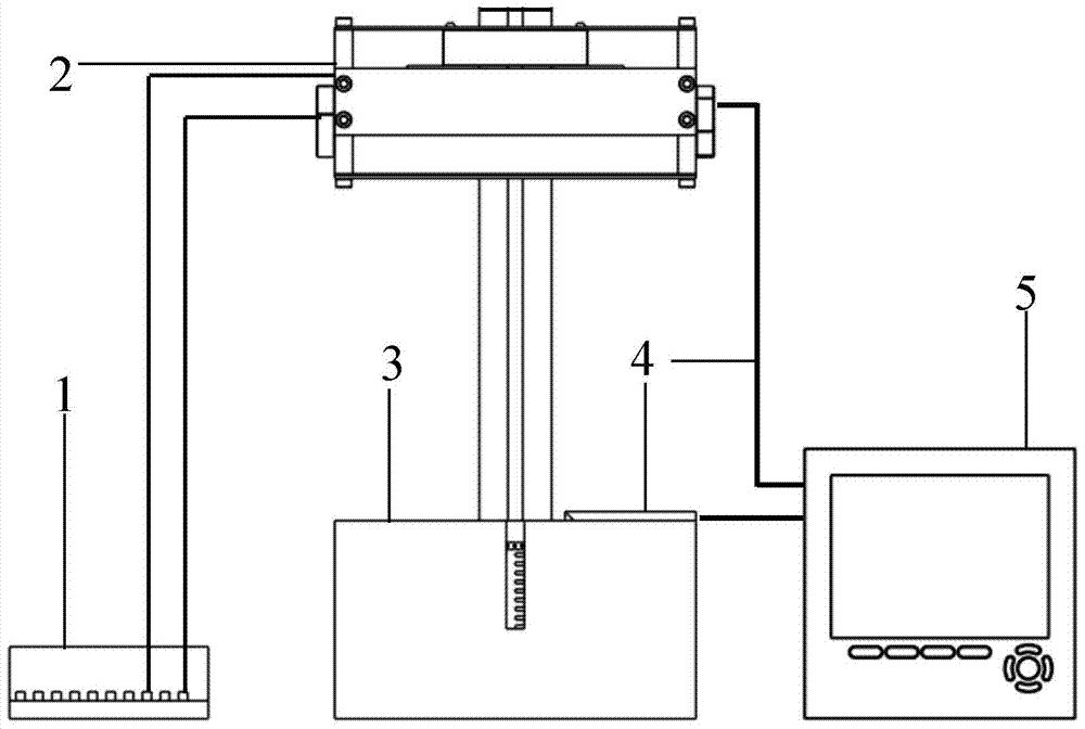
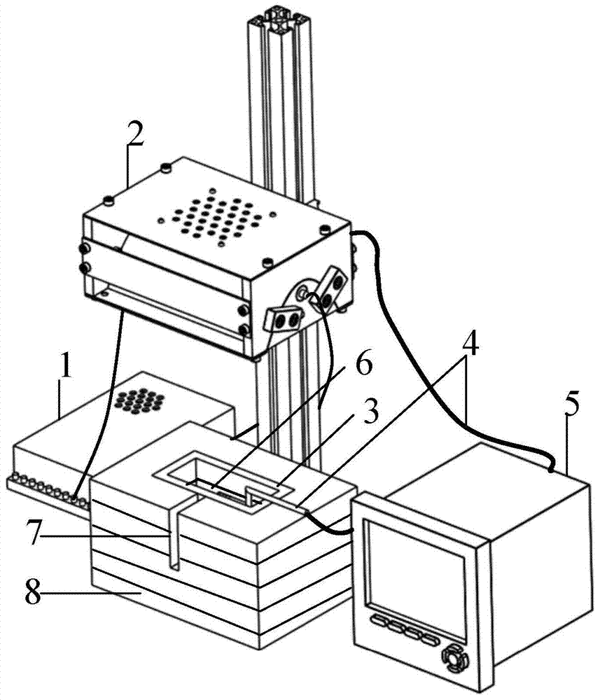
[0027] Specific implementation mode 1, refer to figure 1 , figure 2 , image 3 and Figure 4 Describe this embodiment in detail, the low-melting point translucent material phase change process radiation heating and temperature measuring device described in this embodiment, it includes a stabilized power supply 1, an infrared light box 2, a sample tank 3, n thermocouples 4 and a paperless Recorder 5; n is a positive integer;
[0028] The stabilized power supply 1 supplies power to the infrared light box 2; the sample slot 3 is used to place samples;
[0029] The infrared light box 2 is located directly above the sample tank 3, and is used to generate infrared thermal radiation light, and the infrared thermal radiation light is irradiated onto the sample tank 3 along the vertical direction, so that the sample melts and undergoes a phase change;
[0030] n thermocouples 4 are evenly arranged in the sample tank 3 along the vertical direction, and are used to monitor the chang...
specific Embodiment approach 2
[0034] Specific implementation mode two, refer to image 3 and Figure 5 Describe this embodiment, this specific embodiment is a further description of the low-melting point translucent material phase change process radiation heating and temperature measuring device described in the first specific embodiment, in this embodiment, it also includes a fan 17 and a T-type thermoelectric Even 18;
[0035] The fan 17 is located in the infrared light box 2 and is used to reduce the temperature in the infrared light box 2;
[0036] T-type thermocouple 18 is used for monitoring the temperature in infrared light box 2, and the temperature signal of monitoring is sent to paperless recorder 5, and paperless recorder 5 gathers the temperature signal that T-type thermocouple 18 sends; When T-type thermocouple When the temperature monitored by 18 exceeds the set value, the paperless recorder 5 triggers the relay action to make the fan 17 work to cool the infrared light box 2; when the tempe...
specific Embodiment approach 3
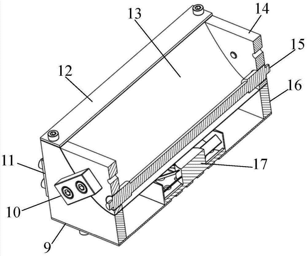
[0039] Specific implementation mode three, refer to image 3 Describe this embodiment, this specific embodiment is a further description of the low-melting point translucent material phase change process radiation heating and temperature measuring device described in the second specific embodiment, in this embodiment, the infrared light box 2 includes a bottom plate 9, Two upper subtypes 14, two lower subtypes 16, reflector 13, connection block 10, halogen black lamp 15 and side connection plate 11; the base plate 9 has ventilation holes; the fan 17 is located on the base plate 9 for ventilation hole;
[0040] The two lower partings 16 are respectively fixed at both ends of the bottom plate 9, and the side connecting plate 11 is fixed on the same side of the two lower partings 16, and is close to the bottom plate 9;
[0041] The reflector 13 is a parabolic reflector; the reflector 13 is sandwiched between the upper parting 14 and the lower parting 16, and the shape of the conta...
PUM
| Property | Measurement | Unit |
|---|---|---|
| diameter | aaaaa | aaaaa |
| reflectance | aaaaa | aaaaa |
Abstract
Description
Claims
Application Information
 - R&D
- Intellectual Property
- Life Sciences
- Materials
- Tech Scout
- Unparalleled Data Quality
- Higher Quality Content
- 60% Fewer Hallucinations
Browse by: Latest US Patents, China's latest patents, Technical Efficacy Thesaurus, Application Domain, Technology Topic, Popular Technical Reports.
© 2025 PatSnap. All rights reserved.Legal|Privacy policy|Modern Slavery Act Transparency Statement|Sitemap|About US| Contact US: help@patsnap.com


