
Multichannel piezoelectric deformable mirror driving power source based on charge driving

A technology for driving a power supply and a deformable mirror, applied in the optical field, can solve the problems affecting the control accuracy of the deformable mirror, the deformation hysteresis effect of the piezoelectric deformable mirror, etc., and achieve the effects of easy control, low cost, and reduction of the hysteresis effect.

Inactive Publication Date: 2018-12-11
NINGBO UNIV
View PDF6 Cites 1 Cited by
  • Summary
  • Abstract
  • Description
  • Claims
  • Application Information

AI Technical Summary

Problems solved by technology

[0003] The purpose of the present invention is to solve the problem that most of the existing piezoelectric deformable mirrors are driven by voltage, which causes hysteresis effect in the deformation of the piezoelectric deformable mirror and affects the control accuracy of the deformable mirror.

Method used


Image

  • Multichannel piezoelectric deformable mirror driving power source based on charge driving
  • Multichannel piezoelectric deformable mirror driving power source based on charge driving
  • Multichannel piezoelectric deformable mirror driving power source based on charge driving

Examples


specific Embodiment approach 1

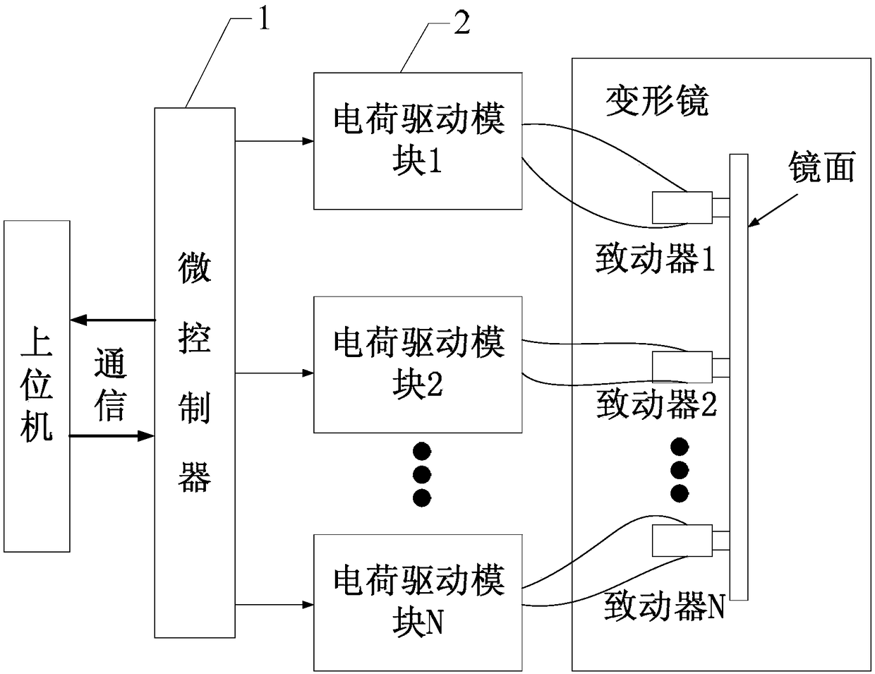
[0019] Specific implementation mode one: refer to figure 1 This embodiment is described in detail. In the charge-driven multi-channel piezoelectric deformable mirror drive power supply described in this embodiment, the deformable mirror is composed of a mirror surface and a plurality of actuators, and the plurality of actuators are arranged below the mirror surface. It is used to receive a voltage signal and convert the voltage signal into strain, so as to form a driving force applied to the mirror surface, thereby changing the surface shape of the mirror surface. It is characterized in that it includes a microcontroller 1 and a plurality of charge drive modules 2,

[0020] The microcontroller 1 is used to control the corresponding charge drive module 2 to complete two actions according to the received instructions: the switching action for charging the capacitor and the switching action for discharging the capacitor,

[0021] Each charge driving module 2 is used to receive th...

specific Embodiment approach 2

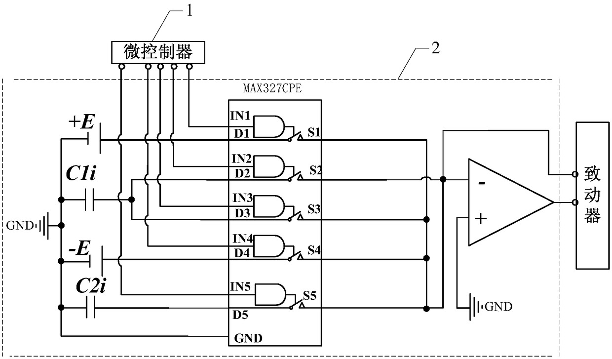
[0024] Specific embodiment two: this embodiment is a further description of the multi-channel piezoelectric deformable mirror drive power based on charge drive described in specific embodiment one. In this embodiment, the capacitor in each charge drive module 2 is one or There are multiple capacitors, and the capacitance values ​​of multiple capacitors differ by 5 to 10 times.

specific Embodiment approach 3

[0025] Embodiment 3: This embodiment further describes the charge-driven multi-channel piezoelectric deformable mirror driving power described in Embodiment 1. In this embodiment, multiple charge-driven modules 2 have the same or different structures.


PUM


Abstract

A multichannel piezoelectric deformable mirror driving power source based on charge driving relates to the optical field, and solves the problem that a conventional deformable mirror driving method often uses a voltage-driven type so that the deformation of a piezoelectric deformable mirror has a hysteresis effect and thus affects the control accuracy of the deformable mirror. A microcontroller isconfigured to control, according to a received instruction, a corresponding charge driving module to perform two operations including a switching operation for charging a capacitor and a switching operation for discharging the capacitor. Each charge driving module is configured to receive the switching operation for charging the capacitor and select a positive voltage source or a negative voltagesource from a plurality of voltage sources of different voltage values to charge the capacitor; and when all capacitors are fully charged, receive the switching operation for discharging the capacitor and control a certain capacitor to discharge to a corresponding actuator such that the actuator generates charges that form a driving force to displace the actuator, thereby changing the surface shape of the mirror. The multichannel piezoelectric deformable mirror driving power source is configured to change the surface shape of the mirror.

Description

technical field [0001] The invention relates to a driving power supply for deformable mirrors, in particular to a charge-driven multi-channel piezoelectric deformable mirror driving power supply, which belongs to the field of optics. Background technique [0002] With the increasing demand for adaptive optics, researchers have done a lot of research work on the key device of the adaptive optics system—deformable mirrors, and developed piezoelectrically driven deformable mirrors, electrostatically driven deformable mirrors, electromagnetically driven deformable mirrors, and liquid crystal spacers. Different types of deformable mirrors such as light modulators. Among them, the deformable mirror driven by piezoelectric material has the advantages of large deformation, high frequency response, low power consumption, high stability, etc., and is currently the most widely used deformable mirror. According to different driving principles, at present, the driving power supply of pi...

Claims


Application Information

Patent Timeline
IPC IPC(8): G02B26/06H02N2/06
CPCG02B26/06H02N2/062
Inventor 喻奇志马剑强李艳杨宗峰李文来彭泰然
Owner NINGBO UNIV
Learn More