
Deformation mirror

A technology of deformable mirror and mirror body, which is applied in the field of deformable mirror, which can solve the problems of heavy deformable mirror, large volume and weight, etc., and achieve the effect of high adjustment accuracy, small volume and small space

Inactive Publication Date: 2013-08-14
TSINGHUA UNIV
View PDF4 Cites 0 Cited by
  • Summary
  • Abstract
  • Description
  • Claims
  • Application Information

AI Technical Summary

Problems solved by technology

However, the existing deformable mirrors are bulky, with large volume and weight, which brings a lot of inconvenience to practical applications.

Method used


Image

  • Deformation mirror
  • Deformation mirror
  • Deformation mirror

Examples


Embodiment Construction

[0023] Embodiments of the present invention are described in detail below, examples of which are shown in the drawings, wherein the same or similar reference numerals designate the same or similar elements or elements having the same or similar functions throughout. The embodiments described below by referring to the figures are exemplary only for explaining the present invention and should not be construed as limiting the present invention.

[0024] In describing the present invention, it should be understood that the terms "center", "longitudinal", "transverse", "upper", "lower", "front", "rear", "left", "right", " The orientations or positional relationships indicated by "vertical", "horizontal", "top", "bottom", "inner" and "outer" are based on the orientations or positional relationships shown in the drawings, and are only for the convenience of describing the present invention and Simplified descriptions, rather than indicating or implying that the device or element refe...


PUM


Abstract

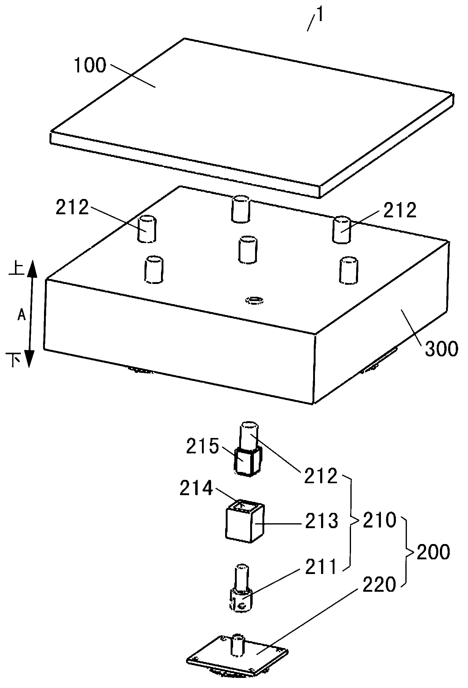
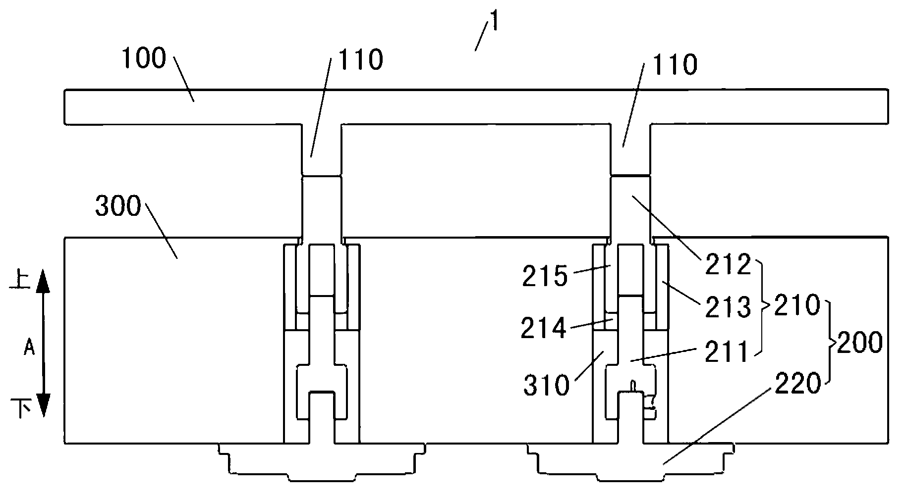
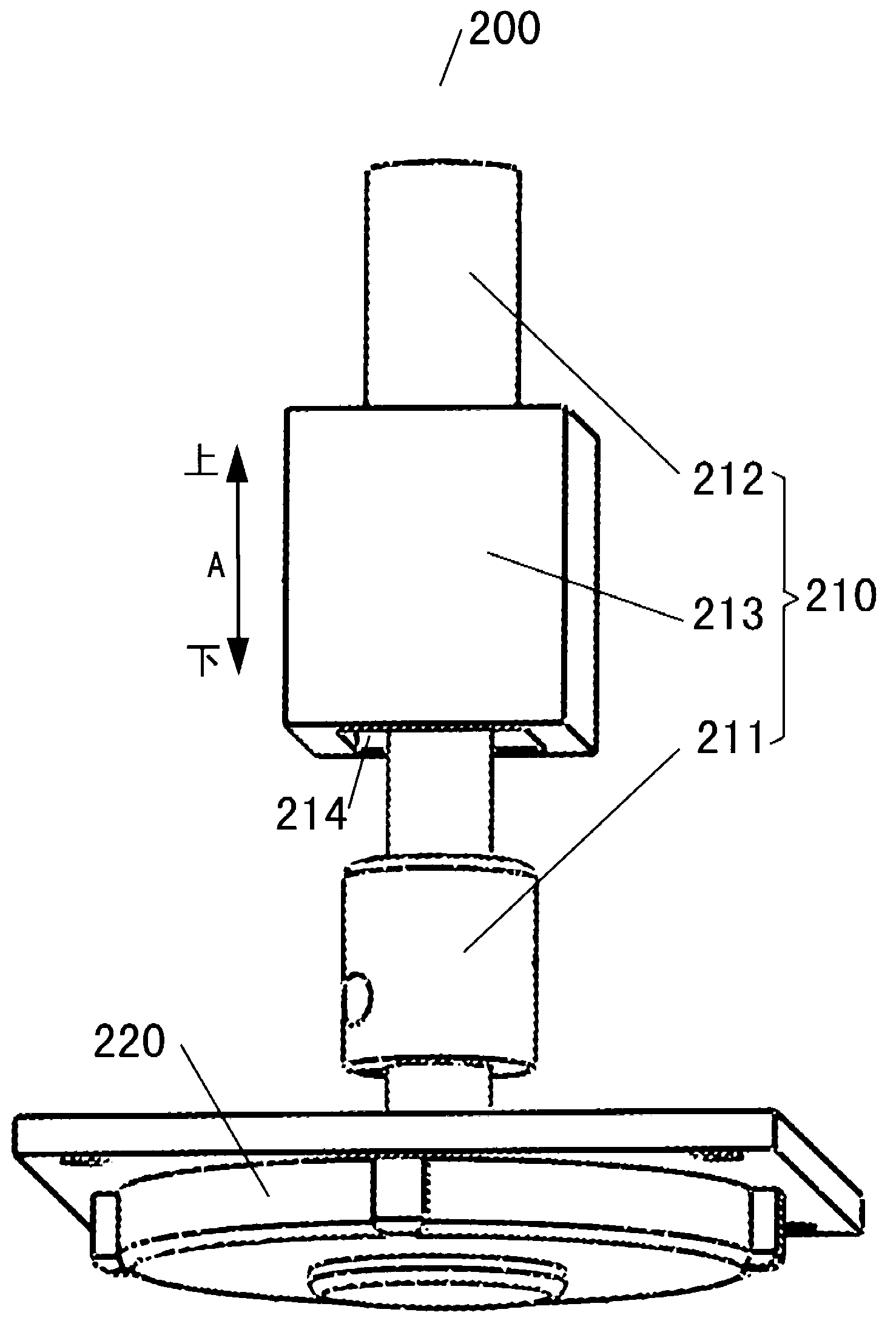
The invention discloses a deformation mirror, comprising a mirror body and at least one brake; the brake comprises a transmission assembly and an ultrasonic motor, and the transmission assembly is connected with the mirror body; and the ultrasonic motor is connected with the transmission assembly and drives the transmission assembly to push the mirror body to change the face shape of the mirror body. The deformation mirror disclosed by the utility model has the advantages of high adjusting accuracy, high efficiency, small size, light weight and the like.

Description

technical field [0001] The invention relates to the field of optics, in particular to a deformable mirror. Background technique [0002] Deformable mirrors, also known as deformable mirrors, are mainly used in various adaptive optics systems. As a wavefront correction device to correct wavefront errors, they play an extremely important role in adaptive optics systems. One of the important components, the research and development of the deformable mirror is related to the correction ability and correction accuracy of the whole adaptive optics system. However, the existing deformable mirrors are bulky, large in volume and weight, which brings a lot of inconvenience to practical applications. Contents of the invention [0003] The present invention aims to solve at least one of the technical problems existing in the prior art. Therefore, an object of the present invention is to provide a deformable mirror with high adjustment precision, high efficiency, small volume and lig...

Claims


Application Information

Patent Timeline
Patent Type & Authority Applications(China)
IPC IPC(8): G02B26/08
Inventor 黄磊巩马理闫平邱运涛柳强张海涛
Owner TSINGHUA UNIV
Learn More