Hydraulic device

A water conservancy and long-cavity technology, applied in hoisting devices, portable lifting devices, etc., can solve problems such as troublesome users, resistance encountered in retracting well ropes, and low degree of automation, so as to improve stability and slide stability , the effect of improving work efficiency

Active Publication Date: 2017-08-18
JIANGSU XIYI HIGH NEW DISTRICT TECH DEV CO LTD
View PDF5 Cites 6 Cited by
  • Summary
  • Abstract
  • Description
  • Claims
  • Application Information

AI Technical Summary

Problems solved by technology

In order to fetch water safely and conveniently, a potter's wheel will be set up next to the well, but the potter's wheel needs to be manually cranked to retract the well rope, and the degree of automation is low. Although some automatic water-lifting machines do not need manual retraction of the well rope, when the rope retracting device body and When there is a horizontal distance in the water well, the well rope is easy to sag, and the well rope will encounter resistance when retracted, and these water lifters cannot adjust the horizontal distance. cause trouble

Method used


Image

  • Hydraulic device
  • Hydraulic device
  • Hydraulic device

Examples


Embodiment Construction

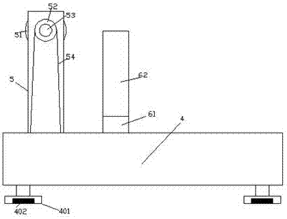
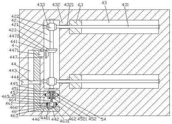
[0022] Such as Figure 1-Figure 5 As shown, a water conservancy device of the present invention includes a base 4 and a rope winding frame 5 fixed on the top left side of the base 4, and the inside of the left side of the base 4 is provided with a first long cavity extending from front to back 42, the abutment 4 on the right side of the first long cavity 42 is provided with guide grooves 43 that correspond up and down and extend left and right, and the left tail of each guide groove 43 is connected with the first long cavity Plates 432 are arranged between the right sides of 42, each of the plates 432 is provided with a through hole 4321, and each of the through holes 4321 is equipped with a first extending to the left and right sides. Screw rod 431, the left side extension tail of the first screw rod 431 extends into the first long cavity 42 and is connected with the left inner wall of the first long cavity 42 in a rotational fit, the first screw rod 431 The extended tail on...


PUM


Abstract

The invention discloses a hydraulic device which comprises a base table and a rope winding frame fixed to the top of the left side of the base table. A first long cavity extending in the front-back direction is formed inside the left side of the base table. Guiding grooves which correspond vertically and extend in the left-right direction are formed in the base table on the right side of the first long cavity. A plate piece is arranged between the right side of the first long cavity and the tail of the left side of each guiding groove. A connection through hole is formed in each plate piece. A first screw rod extending towards the left and right sides is arranged inside each connection through hole in a matched mode. The left side extension tail of each first screw rod extends into the first long cavity and is connected with the inner wall of the left side of the first long cavity in a rotation fit mode, the right side extension tail of each screw rod extends into the corresponding guiding groove and is connected with the inner wall of the right side of the guiding groove in a rotation fit mode. The hydraulic device is simple in structure, the well rope winding efficiency is improved, and a wound well rope is neat.

Description

technical field [0001] The invention relates to the field of water conservancy, in particular to a water conservancy device. Background technique [0002] In areas with abundant groundwater, people will dig wells to extract groundwater for irrigation or living. In order to fetch water safely and conveniently, a potter's wheel will be set up next to the well, but the potter's wheel needs to be manually cranked to retract the well rope, and the degree of automation is low. Although some automatic water-lifting machines do not need manual retraction of the well rope, when the rope retracting device body and When there is a horizontal distance in the water well, the well rope is easy to sag, and the well rope will encounter resistance when retracted, and these water lifters cannot adjust the horizontal distance. cause trouble. Contents of the invention [0003] The technical problem to be solved by the present invention is to provide a water conservancy device, which can sol...

Claims


Application Information

Patent Timeline
Patent Type & Authority Applications(China)
IPC IPC(8): B66D3/18B66D3/26
CPCB66D3/18B66D3/26
Inventor 何海燕
Owner JIANGSU XIYI HIGH NEW DISTRICT TECH DEV CO LTD
Why Eureka
Try Eureka