Continuous filling mechanism

A filling and round tank technology, applied in the field of continuous filling mechanism, can solve the problems of motor failure, transmission error, inaccurate round tank transmission, etc., and achieve the effect of reasonable structure design, avoidance of material leakage, and convenient upgrading.

Inactive Publication Date: 2017-08-18
屠明州
View PDF0 Cites 42 Cited by
  • Summary
  • Abstract
  • Description
  • Claims
  • Application Information

AI Technical Summary

Problems solved by technology

[0002] Filling mainly refers to filling materials into storage equipment. According to the different materials to be filled, filling equipment can be divided into liquid filling machines, oil filling machines, paste filling machines, granule filling machines and powder filling machines. For filling machines, the commonly used storage equipment is round tanks. Round tanks mainly refer to cylindrical airtight containers that can be used to store materials. Round tanks are widely used in our production and life due to their high efficiency and portability. Playing an increasingly important role, the existing round can filling generally uses the filling production line to process the round cans in batches such as filling and capping. Transport to the lower side of the filling mechanism, use the filling mechanism to fill the material into the round tank, and then use the transmission mechanism to transport the filled round tank, because the round tank uses the transmission mechanism during the entire filling and transmission process When the round cans are conveyed, the conveying mechanism is prone to transmission errors when conveying the round cans, and it is easy to cause inaccurate conveyance of the round cans during the entire conveying process, making it difficult to accurately convey the round cans to the lower side of the injection mechanism. And because the injection mechanism needs a certain amount of time to fill the material into the round tank, the transmission mechanism needs to stop the operation of the transmission mechanism when transferring the round can to the lower side of the injection mechanism. The start and stop of the transmission mechanism are generally controlled by the motor , Frequent start and stop of the motor is likely to cause motor failure, and the motor needs to be repaired or replaced, making it difficult for the round can filling production line to run stably for a long period of time. Therefore, the existing round can filling production line is difficult to ensure the efficiency and efficiency of round can filling. The quality cannot meet the needs of production and use

Method used


Image

  • Continuous filling mechanism
  • Continuous filling mechanism

Examples


Embodiment Construction

[0011] In order to further describe the present invention, a specific implementation of a continuous filling mechanism will be further described below in conjunction with the accompanying drawings. The following examples are explanations of the present invention and the present invention is not limited to the following examples.

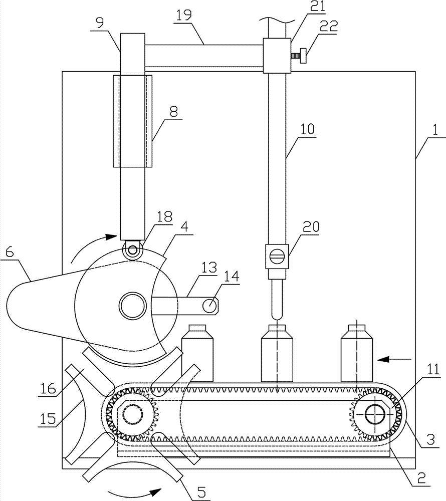
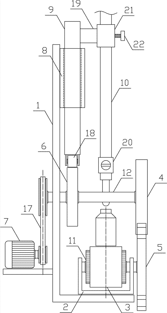
[0012] Such as figure 1 , figure 2 As shown, a continuous filling mechanism of the present invention includes a fixed bracket 1, a transmission bracket 2, a round can conveyor belt 3, a rotating circular plate 4, a slotted rotating plate 5, a rotating cam 6, a rotating motor 7, a lifting sleeve 8, The lifting guide rod 9 and the filling material pipe 10, the transmission bracket 2 is horizontally arranged on the upper side of the fixed bracket 1, and the two sides of the transmission bracket 2 are respectively horizontally connected to a translation pulley 11, and the round can conveyor belt 3 is horizontally arranged on the upper side of the transm...


PUM


Abstract

The invention discloses a continuous filling mechanism, which belongs to the field of material filling machinery and equipment. The invention includes a fixed bracket, a transmission bracket, a round can conveyor belt, a rotating circular plate, a slotted rotary plate, a rotating cam, a rotating motor, a lifting sleeve, a lifting guide rod and a filling material tube, and the round can conveyor belt is horizontally arranged on the transmission bracket. On the side, the rotating circular plate is vertically arranged at one end of the rotating shaft, and the card slot rotating plate is vertically arranged on one side of the translation pulley. Between two adjacent rotating arc surfaces, there are drive slots along the radial direction of the card slot rotating plate. The rotating card slot matching the wheel, the rotating motor and the rotating shaft are connected by a transmission belt transmission, the lifting sleeve is slid along the vertical direction and a lifting guide rod is installed, and the filling material tube is vertically set at one end of the filling support plate . The invention has a reasonable structural design, can quickly, efficiently and smoothly fill the round cans one by one continuously, improves the efficiency and quality of filling, and meets the needs of production and use.

Description

technical field [0001] The invention belongs to the field of material filling machinery and equipment, and in particular relates to a continuous filling mechanism. Background technique [0002] Filling mainly refers to filling materials into storage equipment. Filling equipment can be divided into liquid filling machines, oil filling machines, paste filling machines, granule filling machines and powder filling machines according to the different materials to be filled. For filling machines, the commonly used storage equipment is round tanks. Round tanks mainly refer to cylindrical airtight containers that can be used to store materials. Round tanks are widely used in our production and life due to their high efficiency and portability. Playing an increasingly important role, the existing round can filling generally uses the filling production line to process the round cans in batches such as filling and capping. Transport to the lower side of the filling mechanism, use the ...

Claims


Application Information

Patent Timeline
Patent Type & Authority Applications(China)
IPC IPC(8): B67C3/24
CPCB67C3/24
Inventor 屠明州
Owner 屠明州
Why Eureka
Try Eureka