Underground comprehensive pipe gallery

A technology for integrated pipe corridors and corridors, applied in underwater structures, water conservancy projects, artificial islands, etc., can solve the problems of many openings in the upper part of the pipe corridor, affecting the appearance, messy layout, etc., so as to be suitable for operation management and later maintenance , reduce operation and management costs, and optimize the effect of node structure

Active Publication Date: 2017-08-18
BERIS ENG & RES CORP
View PDF8 Cites 8 Cited by
  • Summary
  • Abstract
  • Description
  • Claims
  • Application Information

AI Technical Summary

Problems solved by technology

[0003] Escape exits, feeding rooms, vents, and power distribution rooms are essential node facilities for the construction of urban comprehensive utility corridors, and are the lifelines to ensure the safe operation of utility corridors. In traditional and conventional methods, each node facility is set up separately or partially combined. The existing problems are: there are many openings in the upper part of the pipe gallery, the layout is messy, the management of accident points and security systems is more difficult, and various functions are relatively scattered, which is not easy for construction management and is not conducive to later maintenance and management. In the gallery, there are safety hazards such as flooding of the pipe gallery. Due to the increase of many entrances and exits, many hydraulic manhole covers need to be installed, which not only affects the appearance but also increases the cost

Method used


Image

  • Underground comprehensive pipe gallery
  • Underground comprehensive pipe gallery
  • Underground comprehensive pipe gallery

Examples


Embodiment Construction

[0026] Embodiments of the technical solutions of the present invention will be described in detail below in conjunction with the accompanying drawings. The following examples are only used to illustrate the technical solutions of the present invention more clearly, and therefore are only examples, rather than limiting the protection scope of the present invention.

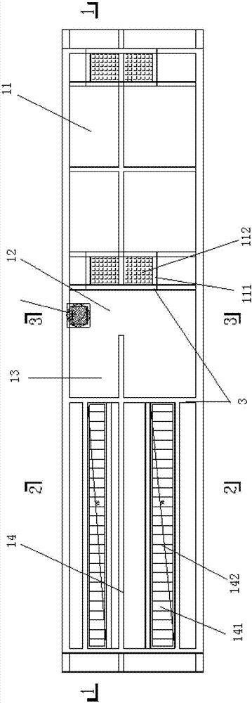
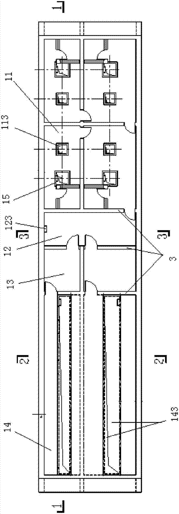
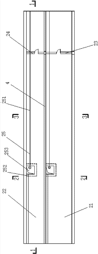
[0027] figure 1 It is a schematic diagram of the ground structure of the underground comprehensive utility gallery according to the embodiment of the present invention, figure 2 It is a schematic diagram of the internal structure of the high-level corridor of the underground comprehensive utility gallery according to the embodiment of the present invention, image 3 It is a schematic diagram of the internal structure of the low-level corridor of the underground comprehensive utility gallery according to the embodiment of the present invention, Figure 4 for figure 1 Schematic diagram of the section along 1-1. ...


PUM


Abstract

The invention relates to an underground comprehensive pipe gallery. The underground comprehensive pipe gallery comprises a high-position gallery body and a low-position gallery body which are constructed under the ground. The high-position gallery body is divided into ventilating rooms, an escape channel, a power distribution room and a feeding room through first partition walls. A plurality of first inlets and outlets are formed in the first partition walls and communicate the ventilating rooms, the escape channel, the power distribution room and the feeding room. The top of each ventilating room is provided with a ventilating opening and a ventilating structure which are exposed out of the ground. The top of the escape channel is provided with an escape opening and an escape well cover which are exposed out of the ground. The top of the feeding room is provided with upper feeding openings and feeding cover plates which are exposed out of the ground. Second inlets and outlets communicating with the low-position gallery body are formed in the bottoms of the ventilating rooms, the escape channel and/or the feeding room. The low-position gallery body is internally provided with a pipeline cabin and a cable cabin. A drainage structure is arranged at the bottoms of the pipeline cabin and the cable cabin. The pipeline cabin is divided into a plurality of sub pipeline cabin bodies. The cable cabin is divided into a plurality of sub cable cabin bodies. The underground comprehensive pipe gallery is small in occupied area, convenient to install and maintain and high in management efficiency.

Description

technical field [0001] The invention belongs to the technical field of urban comprehensive pipe gallery design, and in particular relates to an underground comprehensive pipe gallery. Background technique [0002] The underground comprehensive pipe gallery is a tunnel space built underground in the city. It integrates various engineering pipelines such as power, communication, gas, heating, water supply and drainage, and implements unified planning, unified design, unified construction and management. Critical infrastructure and "lifeline" for operations. It is a municipal public facility that implements unified planning, design, construction and maintenance, and is built underground in the city for laying municipal public pipelines. The construction of urban comprehensive pipe corridor is an important infrastructure to improve people's living conditions. [0003] Escape exits, feeding rooms, vents, and power distribution rooms are essential node facilities for the constru...

Claims


Application Information

Patent Timeline
Patent Type & Authority Applications(China)
IPC IPC(8): E02D29/045
CPCE02D29/10
Inventor 刘晓红
Owner BERIS ENG & RES CORP
Why Eureka
Try Eureka