Construction method achieving fiber continuity at joint in process of pouring concrete for certain times

A construction method and concrete technology, applied in the direction of building, building components, building structure, etc., can solve the problems of reducing the overall performance of the structure, discontinuous fibers, unable to make full use of structural materials, etc., to achieve good promotion prospects, excellent structural performance, The effect of convenient construction

Inactive Publication Date: 2017-08-18
FUZHOU UNIV
View PDF5 Cites 9 Cited by
  • Summary
  • Abstract
  • Description
  • Claims
  • Application Information

AI Technical Summary

Problems solved by technology

[0004] The structure of the above joints does not fundamentally solve the problem of fiber discontinuity at the interface between old and new concrete. Instead, some measures are used to make up for this part of the loss, and the advantages of th

Method used


Image

  • Construction method achieving fiber continuity at joint in process of pouring concrete for certain times
  • Construction method achieving fiber continuity at joint in process of pouring concrete for certain times
  • Construction method achieving fiber continuity at joint in process of pouring concrete for certain times

Examples


Embodiment 1

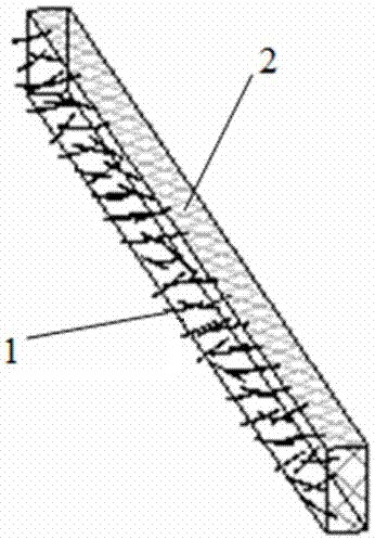
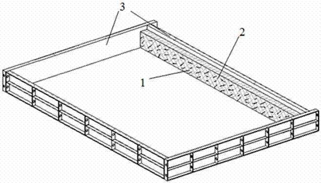
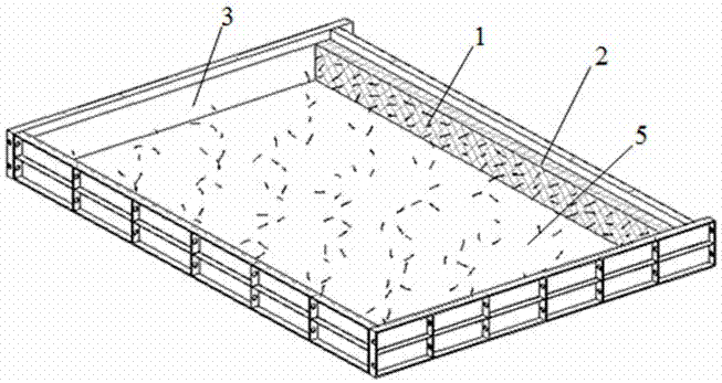
[0024] Such as Figure 1~7 As shown, the construction method of the present invention to achieve fiber continuity at the joints during the staged concrete pouring process is to partially penetrate the fibers 1 into the connecting plate 2 along the length direction, and then install the template 3 at the preset concrete joint interface 4. , The fiber-free side of the connecting plate 2 is tightly attached to the inside of the form 3, and then the concrete 5 is poured and cured; the formwork and the connecting plate at the joint interface are removed, so that the fiber 1 penetrating the connecting plate is exposed to the joint For the joint interface 4, the template 3 is installed and the next concrete 6 is poured and cured, so that the fibers 1 are connected to the adjacent different batches of concrete.

[0025] It specifically includes the following steps:

[0026] 1) Insert the fiber 1 evenly into the connecting plate 2 by pressing, etc., the insertion depth is about half of the...

Embodiment 2

[0039] In the precast concrete structure, each precast concrete structure is connected as a whole by a cast-in-place belt (cast-in-situ section). During the preparation of the precast concrete structure, it is necessary to set the fiber-attached connecting plate on the side connected with the cast-in-situ belt (cast-in-situ section) in advance according to the method in Example 1, so that the side of the obtained precast concrete structure has fibers protruding from The cast-in-situ belt (cast-in-situ section) concrete connection.

[0040] The method of the present invention can increase the connection performance of the interface by adjusting the fiber content and the slenderness ratio on the joint interface, avoiding the behavior of enhancing the mechanical performance of the interface by changing the shape of the interface, setting the connecting piece or setting the special-shaped steel plate, etc. To ensure the performance of the structure at the joints, and reduce engineeri...


PUM


Abstract

The invention discloses a construction method achieving fiber continuity at a joint in the process of pouring concrete for a certain times. The construction method comprises the steps that fibers are made to partly penetrate into a connecting plate (such as foam plastic) in the length direction; then formworks are mounted at a preset concrete joint interface, and the sides, without exposing of the fibers, of the connecting plate is closely attached to the inner sides of the formworks; the formworks and the connecting plate of the joint interface are dismantled after one time of concrete pouring and curing to enable the fibers penetrating into the connecting plates to expose at the joint interface; and the formworks are mounted again, and next-time concrete pouring and curing are conducted, so that the fibers are connected in the adjacent concrete of different batches. According to the construction method, the problem of the fibers, in the joint, of the fiber concrete are discontinuous is solved from the source, joint performance is improved without the need of complex joint modes such as changing of the joint shape and arranging of shear keys or irregular steel plates, construction is convenient, structure performance is excellent, the engineering construction cost can be reduced significantly, and good popularization prospects are achieved.

Description

Technical field [0001] The invention belongs to the technical field of civil engineering, and in particular relates to a construction method for realizing fiber continuity at joints during concrete pouring in stages. Background technique [0002] In order to improve the crack resistance of concrete structures, fibers are often added to concrete to form fiber concrete structures. These dispersed fibers can effectively prevent the expansion of micro-cracks and the formation of macro-cracks in the concrete, significantly improve the bending, tensile, corrosion and fatigue resistance of the concrete structure, and make the structure have better ductility. Concrete structures are divided into precast and cast-in-place construction methods. The precast structures are generally connected by cast-in-place belts (cast-in-situ sections). If the cast-in-situ structure cannot be completed at one time, construction joints need to be set. The situation will involve the connection of the old a...

Claims


Application Information

Patent Timeline
IPC IPC(8): E04B1/682
CPCE04B1/68
Inventor 赵秋陈宝春杨建平杜阳
Owner FUZHOU UNIV
Why Eureka
Try Eureka