
Air supply device

A technology of air supply device and fan, which is applied to pump devices, components of pumping devices for elastic fluids, non-variable pumps, etc. It can solve the problems of low heat exchange efficiency of air supply devices and achieve faster circulation speed , shorten the air circulation loop, improve the effect of heat exchange efficiency

Active Publication Date: 2017-08-18
GREE ELECTRIC APPLIANCES INC
View PDF7 Cites 0 Cited by
  • Summary
  • Abstract
  • Description
  • Claims
  • Application Information

AI Technical Summary

Problems solved by technology

[0005] The main purpose of the present invention is to provide an air supply device to solve the problem of low heat exchange efficiency of the air supply device in the prior art

Method used


Image

  • Air supply device
  • Air supply device
  • Air supply device

Examples


Embodiment 2

[0057] The difference from Embodiment 1 is that in this embodiment, there is only the first gas path, and there is no second gas path.

[0058] That is to say, the central air outlet, the second air inlet structure, the connecting pipe, and the connecting port on the inner shell are all removed, and only the first air path is retained. Compared with the first embodiment, the air supply volume will be reduced.

Embodiment 3

[0060] The difference from Embodiment 1 is that in this embodiment, the second air inlet structure is not provided, and only the communication opening on the inner shell remains in the second air path.

[0061] In this way, part of the airflow in the shell flows out through the annular air outlet, and the other part passes through the communication opening and flows out through the central air outlet.


PUM


Abstract

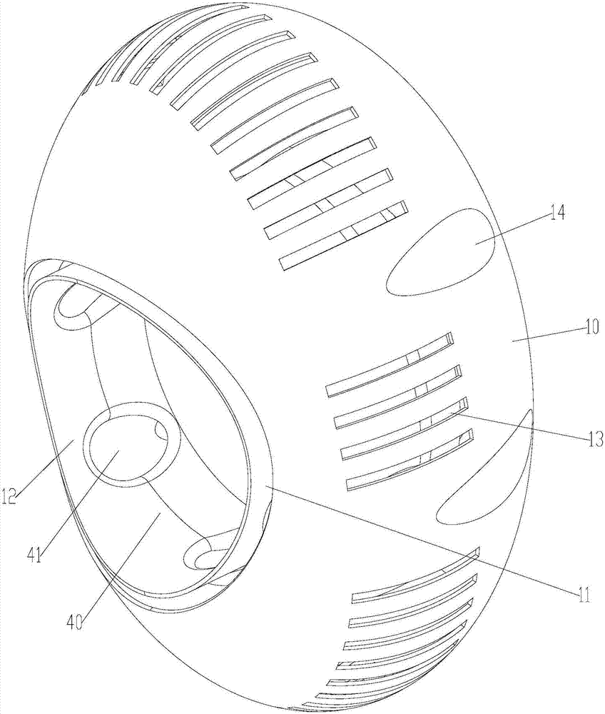
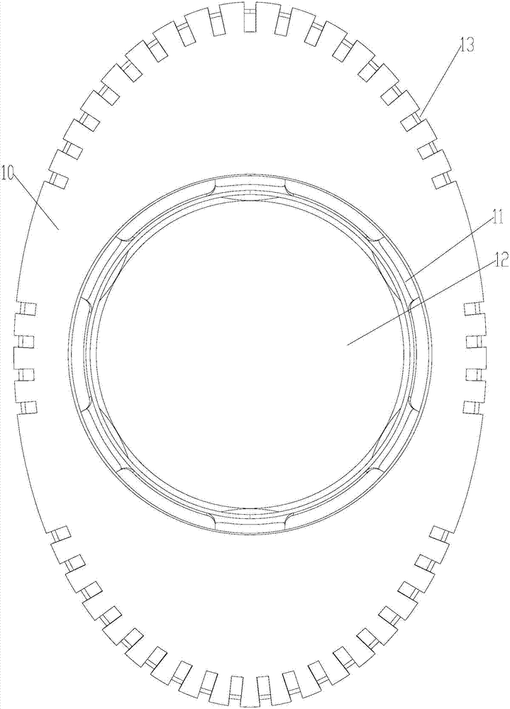
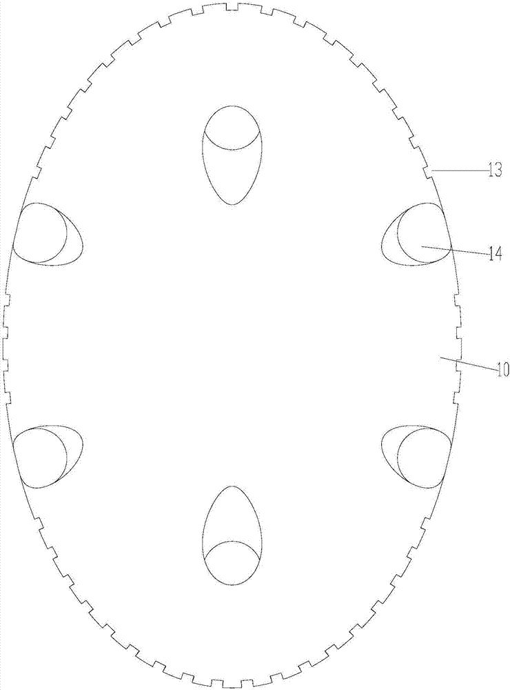
The invention provides an air supply device which comprises a shell, a draught fan and a first gas way. The shell is provided with a first air inlet structure and a ring-shaped air outlet. The ring-shaped air outlet is located in the front end of the shell, the rear end of the shell is opposite to the front end of the shell, and the first air inlet structure is closed to the front end of the shell relative to the rear end of the shell. The draught fan is arranged in the shell. Gas in the first gas way passes through the first air inlet structure and the draught fan and then flows out of the ring-shaped air outlet. By means of the air supply device, the problem that the heat exchange efficiency of the air supply device is low in the prior art is solved.

Description

technical field [0001] The present invention relates to the technical field of household appliances, in particular to an air supply device. Background technique [0002] With the improvement of living standards, people put forward higher requirements for the comfort of the living environment, and there are more and more types of air supply devices. [0003] Most of the existing air supply devices are ordinary fans with blades, air conditioners with heat exchangers, air supply devices without blades, etc. [0004] For the air supply device without fan blades, the air inlet structure is usually located at the rear end of the air supply device, and the air outlet is usually located at the front end of the air supply device, so that the heat exchange efficiency of the air supply device is low and the energy consumption is high. Contents of the invention [0005] The main purpose of the present invention is to provide an air supply device to solve the problem of low heat excha...

Claims


Application Information

Patent Timeline
Patent Type & Authority Applications(China)
IPC IPC(8): F04D25/08F04D29/40
CPCF04D25/08F04D29/403
Inventor 贾铌柳洲梁浩马恒川尚勇
Owner GREE ELECTRIC APPLIANCES INC
Learn More