A stainless steel tube that is easy to disassemble

A technology of stainless steel pipes and steel pipes, applied in the direction of pipes, rigid pipes, pipes/pipe joints/fittings, etc., can solve the problems of non-removal, troublesome replacement of clamping clamps, and high cost, ensuring connection strength, saving installation time, and preventing good leak effect

Active Publication Date: 2018-04-10
李江
View PDF7 Cites 0 Cited by
  • Summary
  • Abstract
  • Description
  • Claims
  • Application Information

AI Technical Summary

Problems solved by technology

The installation methods of stainless steel pipe fittings are generally clamping type and socket type argon arc welding. Since the clamping type installation requires a large hydraulic pressure, and when installing pipe fittings of different specifications, different clamping pliers need to be used, and it is very difficult to replace the clamping clamps. Trouble; the socket welding type needs to adopt argon arc welding technology, which requires high technical requirements for the installation workers, and requires long-term training for the installation workers, and the cost is relatively high
In the process of pipeline laying, the existence of obvious pipe joints will have a certain impact on the construction. If a whole long steel pipe is used, it will be difficult to manufacture and transport. Therefore, it is hoped to use multi-section shorter steel pipes. If multi-section steel pipes are used for welding, they cannot be disassembled. Long steel pipes that are too smooth require a large clamping force when disassembled, which is likely to cause irreversible damage to the surface of the steel pipes, and special space must be reserved for the protruding connectors during transportation.

Method used


Image

  • A stainless steel tube that is easy to disassemble
  • A stainless steel tube that is easy to disassemble
  • A stainless steel tube that is easy to disassemble

Examples


Embodiment Construction

[0020] The following will clearly and completely describe the technical solutions in the embodiments of the present invention with reference to the accompanying drawings in the embodiments of the present invention. Obviously, the described embodiments are only some, not all, embodiments of the present invention. Based on the embodiments of the present invention, all other embodiments obtained by persons of ordinary skill in the art without making creative efforts belong to the protection scope of the present invention.

[0021] It should be understood that terms such as "having", "comprising" and "including" used herein do not exclude the presence or addition of one or more other elements or combinations thereof.

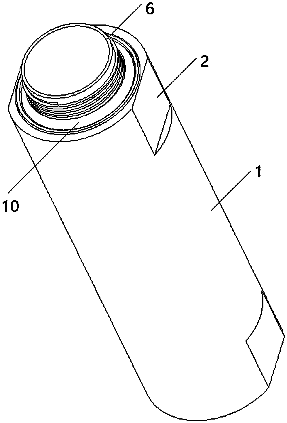
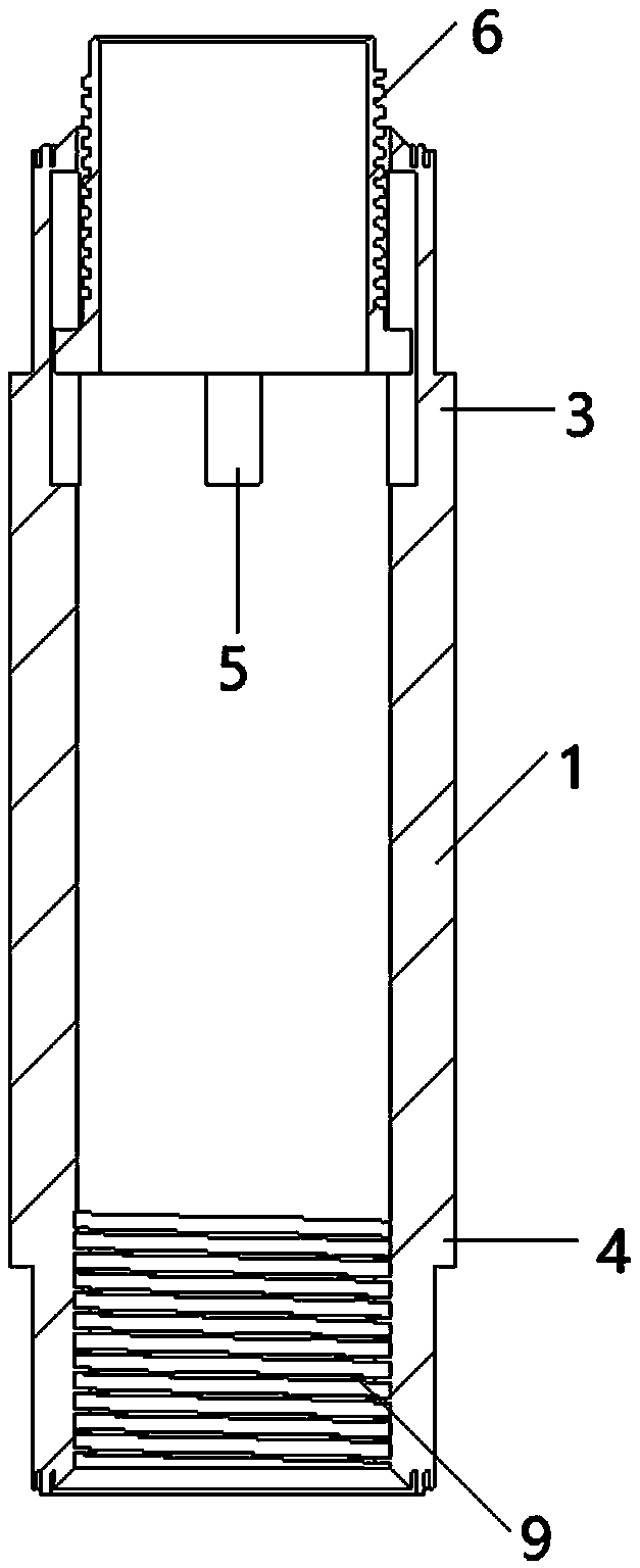
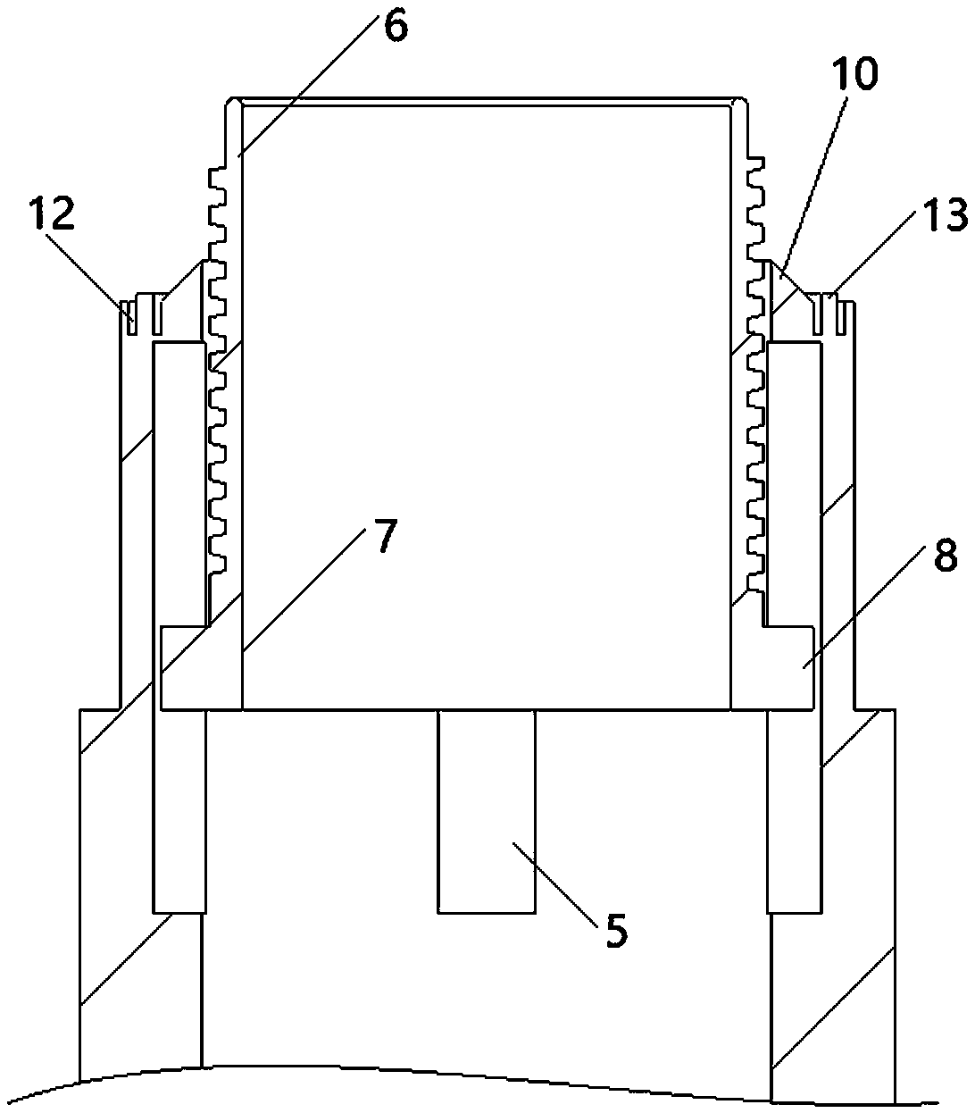
[0022] see Figure 1-4 , the present invention provides a technical solution: comprising a steel pipe body 1, flat grooves 2 are provided at both ends of the steel pipe body 1, the opening forms of the flat grooves 2 at both ends of the steel pipe body 1 are not req...


PUM

PropertyMeasurementUnit
tensile strengthaaaaaaaaaa
elongation at breakaaaaaaaaaa

Abstract

The invention discloses a stainless steel tube convenient to disassemble and assemble. The stainless steel tube comprises a steel tube main body, the two ends of the steel tube main body are provided with flat opening grooves, and the steel tube main body comprises an active connecting end and a passive connecting end; and four evenly-arranged sliding grooves are uniformly formed in the periphery of the inner wall of the active connecting end, a threaded sleeve is arranged in the middle of the active connecting end, a sliding ring is arranged below the threaded sleeve, and sliding blocks matched with the sliding grooves are uniformly arranged on the periphery of the sliding ring. According to the stainless steel tube, the sliding grooves are matched with the sliding blocks, thus the threaded sleeve can stretch out and draw back in the axial direction of the steel tube main body, and on the premise of guaranteeing connection strength, the stainless steel tube is convenient to transport; due to the combination of a positioning inclined table and a positioning inclined groove, the axial positioning between two steel tube main bodies can be conveniently and rapidly carried out, and thus the installation time is saved; sealing gaskets arranged in sealing grooves are relatively good in leakage stopping effect; and due to the flat opening grooves, proper tools can be selected to clamp the steel tube main body conveniently, and the surface of the steel tube main body is prevented from being damaged.

Description

technical field [0001] The invention relates to the technical field of stainless steel pipe fittings, in particular to a stainless steel pipe that is easy to assemble and disassemble. Background technique [0002] In modern life water supply and drainage and direct drinking water piping systems, stainless steel pipe fittings are the most widely used pipe fittings. Because the metallographic structure of stainless steel is very stable and corrosion-resistant, it is widely used in water pipelines, oil pipelines and various liquid chemical material pipelines. The installation methods of stainless steel pipe fittings are generally clamping type and socket type argon arc welding. Since the clamping type installation requires a large hydraulic pressure, and when installing pipe fittings of different specifications, different clamping pliers need to be used, and it is very difficult to replace the clamping clamps. Trouble; the socket welding type needs to adopt argon arc welding t...

Claims


Application Information

Patent Timeline
Patent Type & Authority Patents(China)
IPC IPC(8): F16L9/02F16L21/08
CPCF16L9/02F16L21/08
Inventor 李江
Owner 李江
Why Eureka
Try Eureka