Anti-icing cylindrical pressure probe

A probe and cylindrical technology, which is applied in the field of anti-icing cylindrical pressure probes, can solve problems such as icing of cylindrical probes, and achieve the effects of preventing icing problems, ensuring accuracy and having a simple structure.

Active Publication Date: 2017-08-18
BEIHANG UNIV
View PDF5 Cites 1 Cited by
  • Summary
  • Abstract
  • Description
  • Claims
  • Application Information

AI Technical Summary

Problems solved by technology

[0003] The main technical problem to be solved by the present invention is to provide an anti-icing cylindrical pressure probe, which can solve the problem of freezing of the cylindrical probe during icing experiments

Method used


Image

  • Anti-icing cylindrical pressure probe
  • Anti-icing cylindrical pressure probe
  • Anti-icing cylindrical pressure probe

Examples


Embodiment 1

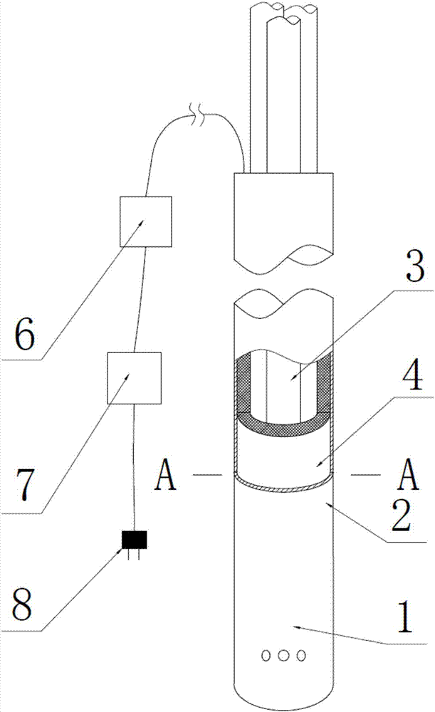
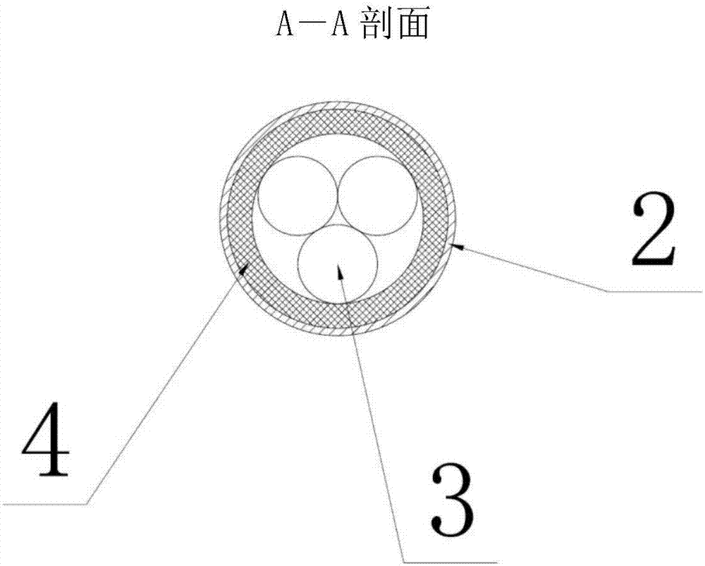
[0027] Such as figure 1 , figure 2 and image 3 As shown, an anti-icing column-shaped pressure probe is introduced in this embodiment, which includes a probe head (1), a probe rod (2), and a pressure introduction tube (3); the anti-icing column-shaped pressure probe The needle is a columnar structure, and the pressure-sensing hole on the head can be single-hole, double-hole, three-hole or four-hole structure; the probe rod (2) is a hollow sleeve rod, and the end of the probe is provided with a probe head (1) , the probe head (1) is welded to the probe rod (2), and the probe head (1) blocks the hollow part of the probe rod (2); the middle sleeve pressure guide tube (3) of the probe rod, Each pressure induction tube (3) is brazed together and extends in a direction parallel to the axis of the probe rod (2), and the end of each pressure induction tube (3) is inserted into the pressure sensing tube of the probe head (1). holes and welded together.

[0028] In this embodiment,...

Embodiment 2

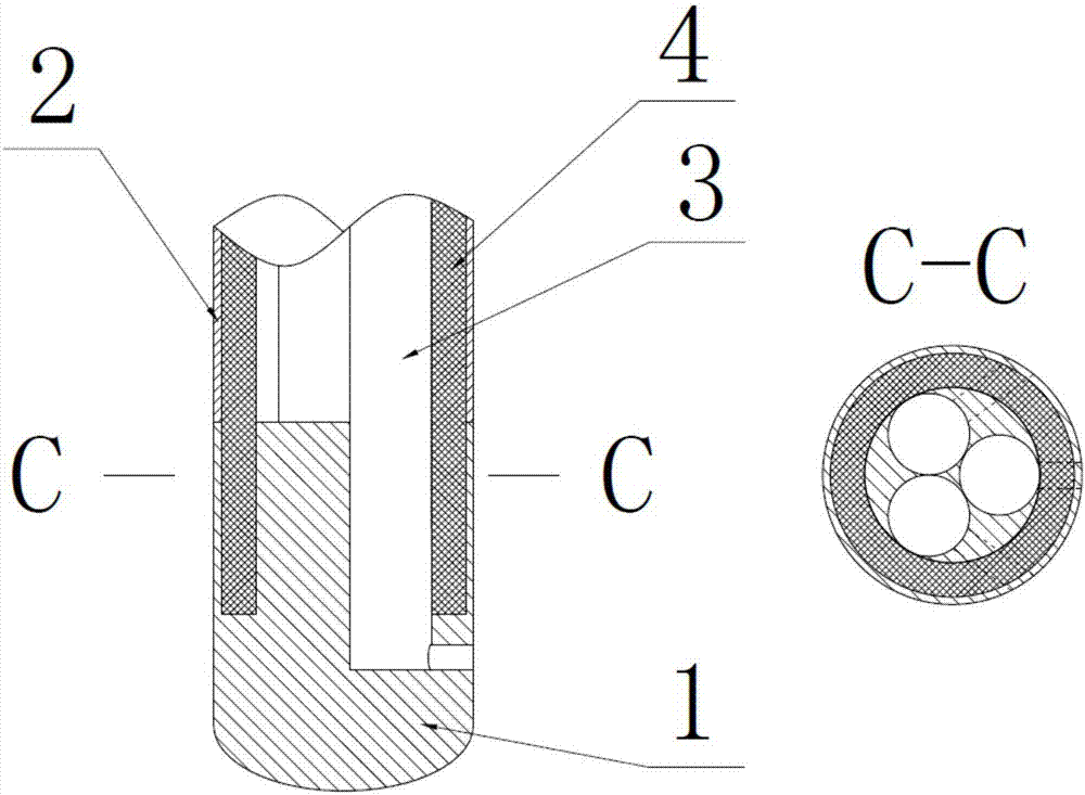
[0035] Such as Figure 4 , Figure 5 and Figure 6 As shown, an anti-icing column pressure probe is introduced in this embodiment, which includes a probe head (1), a probe rod (2), and a pressure introduction tube (3); the anti-icing column-shaped pressure probe The needle is a columnar structure, and the pressure-sensing hole on the head can be single-hole, double-hole, three-hole or four-hole structure; the probe rod (2) is a hollow sleeve rod, and the end of the probe is provided with a probe head (1) , the probe head (1) is welded to the probe rod (2), and the probe head (1) blocks the hollow part of the probe rod (2); the middle sleeve pressure guide tube (3) of the probe rod, Each pressure induction tube (3) is brazed together and extends in a direction parallel to the axis of the probe rod (2), and the end of each pressure induction tube (3) is inserted into the pressure sensitive tube of the probe head (1). holes and welded together.

[0036]In this embodiment, ele...

Embodiment 3

[0042] This embodiment is based on any one of the above-mentioned embodiments one and two, and also has the following technical features: the tail of the heating film (4) or the heating rod (5) is wired to pass through the probe rod (2), and the terminal that passes through The part is provided with a plug (8) connected to the power supply.

[0043] Through the above settings, the heating film (4) or heating rod (5) of the cylindrical pressure probe is connected to the external power supply through the wiring provided with the plug (8), so as to realize the heating of the heating film (4) or the heating rod (5). The rod (5) serves the purpose of heating the power supply.

[0044] In this embodiment, in order to improve the accuracy of the heating control of the cylindrical pressure probe, a temperature control device (6) is provided on the wiring between the tail of the heating film (4) or the heating rod (5) and the plug (8). , transformer (7); described temperature control ...


PUM

PropertyMeasurementUnit
diameteraaaaaaaaaa
thicknessaaaaaaaaaa

Abstract

The invention discloses an anti-icing cylindrical pressure probe comprising a probe head (1), a probe rod (2), and pressure guide tubes (3). The head of the cylindrical probe can be a single-hole, dual-hole, three-hole or four-hole structure. The probe head (1) and the probe rod (2) are welded together. The pressure guide tubes (3) are brazed together, and are sheathed in the probe rod (2). An electro-thermal film (4) coats the pressure guide tubes (3), or electric heating rods (5) are distributed uniformly around the pressure guide tubes (3). By arranging the electro-thermal film (4) or the electric heating rods (5) inside the probe, the pressure guide tubes (3) at the head and rod of the cylindrical pressure probe can be heated in an effective and timely manner, the temperature of the cylindrical pressure probe can be controlled in real time and accurately, the cylindrical pressure probe can be prevented from being iced and affecting a measured flow field in ice wind tunnel experiment or altitude test, and the accuracy of measurement data is ensured.

Description

technical field [0001] The invention relates to the technical field of engine test anti-icing, in particular to an anti-icing cylindrical pressure probe, which can effectively prevent the cylindrical pressure probe from freezing, such as preventing the The shaped pressure probe freezes in the ice wind tunnel experiment and the high-altitude platform experiment, and does not affect the measured flow field, ensuring the accuracy of the measurement data. Background technique [0002] When the aircraft is flying in icy weather conditions, the supercooled water droplets will hit the windward side of the aircraft and cause icing. The icing of the engine inlet and the cold air inlet will lead to insufficient bleed air. If the ice layer falls off, it will be damaged. Components inside the air intake that adversely affect the performance of the aircraft. Ice wind tunnel test is the most basic means to carry out research on icing and anti-icing methods of aircraft and components. Th...

Claims


Application Information

Patent Timeline
Patent Type & Authority Applications(China)
IPC IPC(8): G01L23/26G01M9/06G01M15/02
CPCG01L23/26G01M9/065G01M15/02
Inventor 马宏伟李鑫
Owner BEIHANG UNIV
Why Eureka
Try Eureka