Supercharge Your Innovation With Domain-Expert AI Agents!

An energy-saving electromagnetic switch

An electromagnetic switch, electromagnet technology, applied in electromagnetic relays, circuits, relays and other directions, can solve the problems of reducing circuit maintenance efficiency, power loss, magnetization, etc., to avoid the phenomenon of iron core magnetization, prolong service life, and good application value. Effect

Active Publication Date: 2019-06-11
NANHUA UNIV
View PDF6 Cites 0 Cited by
  • Summary
  • Abstract
  • Description
  • Claims
  • Application Information

AI Technical Summary

Problems solved by technology

[0002] An electromagnetic switch is a device that is convenient for remote control of line switching or on-off. However, there are many problems with the electromagnetic switch in the prior art: on the one hand, the electromagnetic switch in the prior art often requires continuous power supply to the electromagnet to maintain the conduction of the power transmission end. , and long-term energization of the electromagnet will bring two problems: 1. Power loss, the electromagnet that is turned on will consume power; 2. The iron core of the electromagnet is magnetized. It is easy to be magnetized, and once the iron core is magnetized, it means that the electromagnetic switch is invalid; on the other hand, the electromagnetic switch in the prior art does not have a feedback function, and the remote control terminal can only judge the electromagnetic switch on the line by detecting the on-off of the transmission terminal. However, in a complex power grid, multiple lines are intertwined together, and multiple electromagnetic control switches are required. If the circuit fails due to the failure of the electromagnetic switch, only the working conditions of the electromagnetic control switches are detected one by one. Only then can the location of the faulty switch be determined, which will greatly reduce the efficiency of circuit maintenance

Method used


Image

  • An energy-saving electromagnetic switch
  • An energy-saving electromagnetic switch

Examples


Embodiment Construction

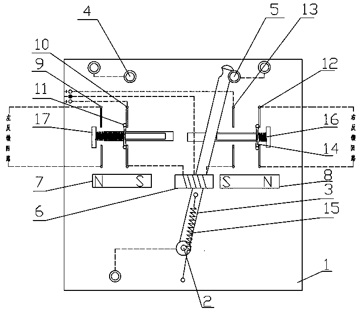
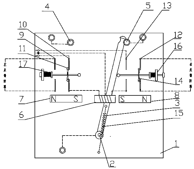
[0021] In the description of the present invention, it should be understood that the orientations or positional relationships indicated by the terms "left", "right", and "top" are based on the orientations or positional relationships shown in the drawings, and are only for the convenience of describing the present invention and simplified descriptions, rather than indicating or implying that the device or element referred to must have a specific orientation, be constructed and operate in a specific orientation, and thus should not be construed as limiting the invention.

[0022] For the convenience of expression, part of the text in this application document is expressed as "connection" or "connection" for the contact between the moving contact and the terminal. It should be noted that this is only for the convenience of expression, and its essence is still the contact of the moving contact. The two contacts make contact with the contacts on the terminal block so that the termi...


PUM


Abstract

The invention relates to the technical field of a switch, specifically to an energy-saving electromagnetic switch. The energy-saving electromagnetic switch comprises a base, a rotary shaft arranged on the base and a conductive swinging rod which can swing around the rotary shaft; the conductive swinging rod is connected with an input terminal; first static contacts and second static contacts are arranged on the two sides of the conductive swinging rod respectively; the first static contacts and the second static contacts are connected with corresponding current output terminals respectively; an electromagnet is fixedly mounted on the rod body of the conductive swinging rod; a left permanent magnet and a right permanent magnet with opposite polarities are arranged on the base on the two sides of the electromagnet; the iron core of the electromagnet is wound with a first coil and a second coil; the first coil and the second coil are powered on to generate electric fields with opposite polarities; and the base is also provided with a positive electrode wiring terminal and a negative electrode wiring terminal used for supplying power for the first coil and the second coil.

Description

technical field [0001] The invention relates to the technical field of switches, in particular to an energy-saving electromagnetic switch. Background technique [0002] An electromagnetic switch is a device that is convenient for remote control of line switching or on-off. However, there are many problems with the electromagnetic switch in the prior art: on the one hand, the electromagnetic switch in the prior art often requires continuous power supply to the electromagnet to maintain the conduction of the power transmission end. , and long-term energization of the electromagnet will bring two problems: 1. Power loss, the electromagnet that is turned on will consume power; 2. The iron core of the electromagnet is magnetized. It is easy to be magnetized, and once the iron core is magnetized, it means that the electromagnetic switch is invalid; on the other hand, the electromagnetic switch in the prior art does not have a feedback function, and the remote control terminal can ...

Claims


Application Information

Patent Timeline
Patent Type & Authority Patents(China)
IPC IPC(8): H01H51/01H01H51/27
CPCH01H51/01H01H51/27
Inventor 陈文辉罗扬刘兵
Owner NANHUA UNIV
Features
  • R&D
  • Intellectual Property
  • Life Sciences
  • Materials
  • Tech Scout
  • Unparalleled Data Quality
  • Higher Quality Content
  • 60% Fewer Hallucinations
Learn More