
A cable bridge laying device

A technology of cable tray and jacking device, which is applied to cable laying equipment, cable installation, cable installation in underground pipelines, etc. The effect of construction difficulty, reducing casualties and reducing safety hazards

Active Publication Date: 2019-01-22
DEYANG POWER SUPPLY COMPANY STATE GRID SICHUAN ELECTRIC POWER +1
View PDF5 Cites 0 Cited by
  • Summary
  • Abstract
  • Description
  • Claims
  • Application Information

AI Technical Summary

Problems solved by technology

[0002] When laying cables on the cable bridge in the basement, the motorized traction equipment cannot be used, and manual traction is completely used, which is slow and requires a lot of labor, which is dangerous. At the same time, the cable bridge will collapse due to the incorrect direction of force, causing injury accidents

Method used


Image

  • A cable bridge laying device
  • A cable bridge laying device
  • A cable bridge laying device

Examples


Embodiment 1

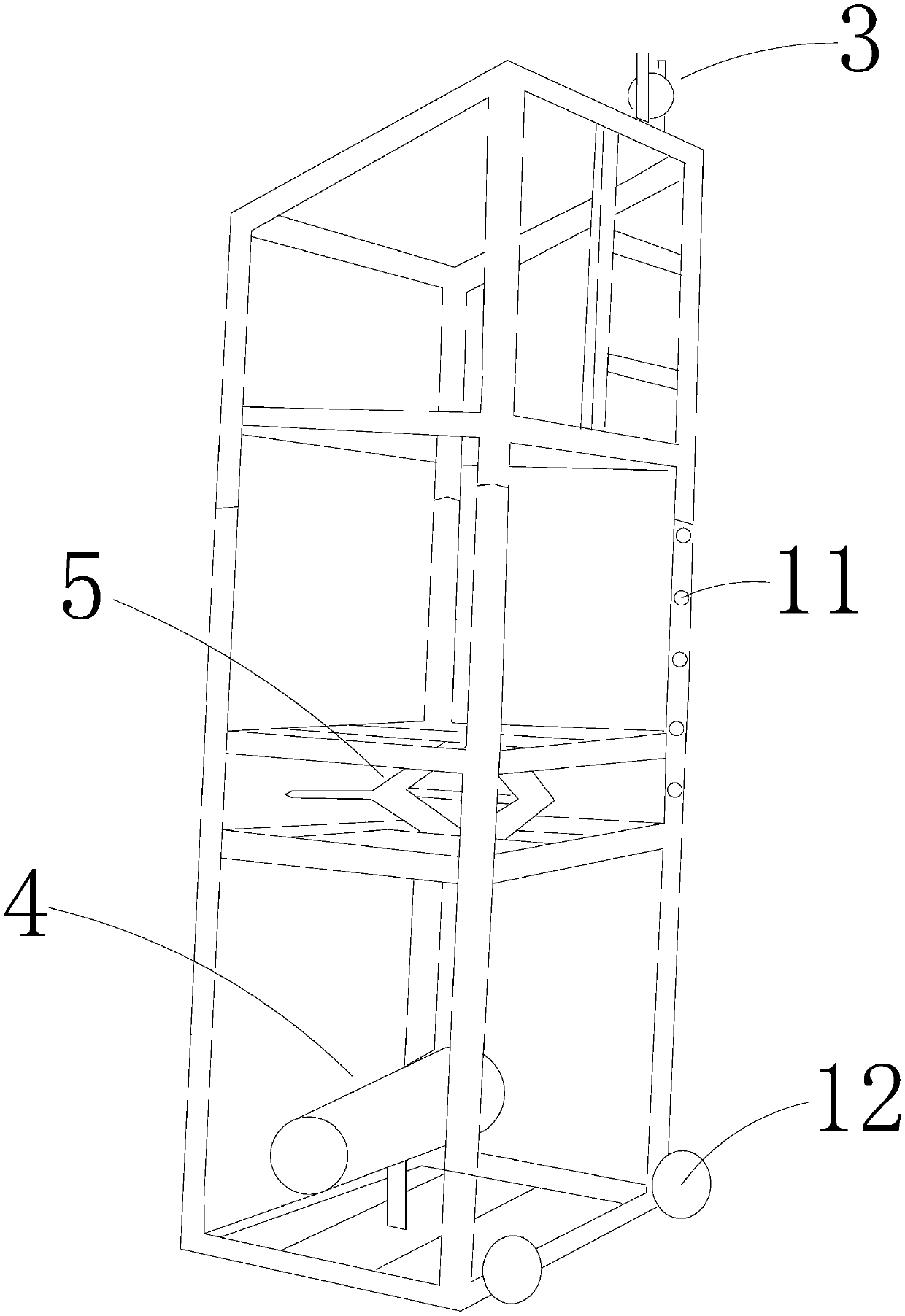
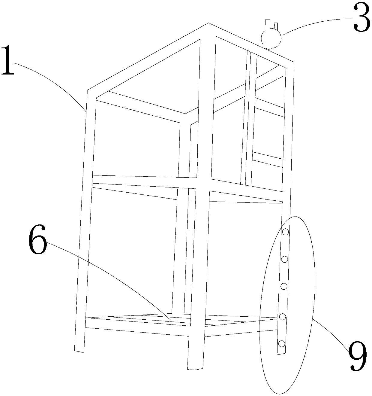
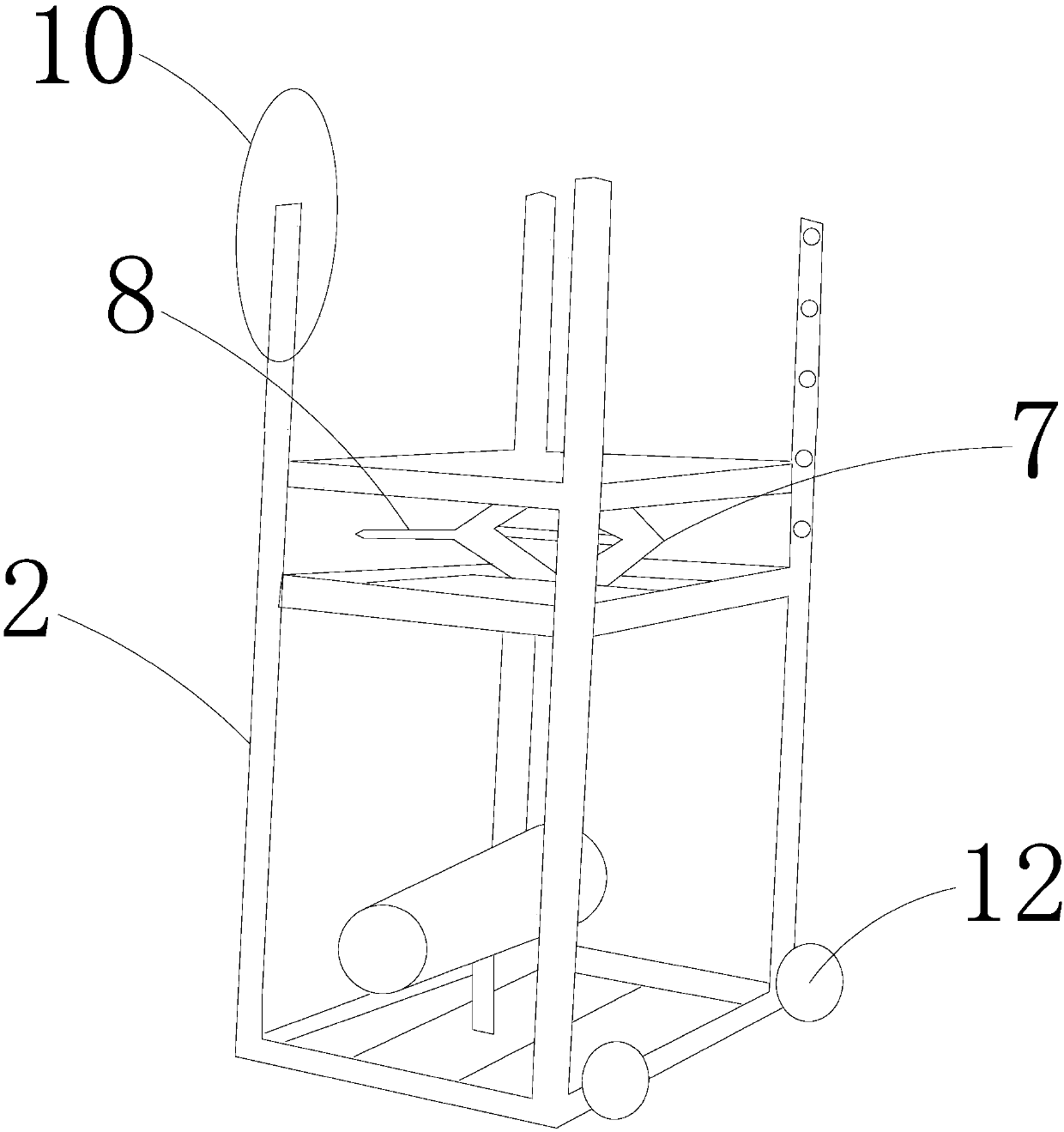
[0026] A cable tray laying device, including a bracket, a pulley 3 and a motor 4, the bracket includes two parts, respectively an upper bracket 1 and a lower bracket 2, the pulley is installed on the upper bracket, and the motor is installed on the The lower bracket is provided with a jacking device 5 between the upper bracket and the lower bracket. Electric towing cable traction rope, the pulley is used as the point where the traction cable changes the force direction.

[0027] The upper end of the jacking device is in contact with the upper bracket, and the lower end of the jacking device is in contact with the lower bracket. Both the upper bracket and the lower bracket are provided with a beam 6, the jacking device is fixed on the beam of the lower bracket, and the upper end of the jacking device withstands the beam of the upper bracket. Considering the different heights of the cable trays, the jacking device is designed as a regulator, which can lay out the cables of diff...


PUM


Abstract

The invention relates to the technical field of cable laying, specifically to a cable bridge laying apparatus. The cable bridge laying apparatus comprises a bracket, a pulley and a motor; the bracket comprises two parts, including an upper part and a lower part; the pulley is mounted on the upper bracket; the motor is mounted on the lower bracket; and a jacking apparatus is arranged between the upper bracket and the lower bracket. By virtue of the cable bridge laying apparatus, the problem of difficulty in cable expansion and placement in cable bridge construction of a basement of an urban high-layer building can be solved; and in addition, electrical cable dragging is adopted, so that construction difficulty is lowered.

Description

technical field [0001] The invention relates to the technical field of cable laying, in particular to a cable bridge laying device. Background technique [0002] When laying cables on the cable bridge in the basement, the motorized traction equipment cannot be used, and manual traction is completely used, which is slow and requires a lot of labor, which is dangerous. At the same time, the cable bridge will collapse due to the incorrect direction of force, causing injury accidents. Contents of the invention [0003] Aiming at the problems existing in the prior art, a cable tray laying device capable of laying cables in a basement with high efficiency and high safety is provided. [0004] The technical scheme adopted in the present invention is: [0005] A cable tray laying device, including a bracket, a pulley and a motor, the bracket includes two parts, respectively an upper bracket and a lower bracket, the pulley is installed on the upper bracket, and the motor is instal...

Claims


Application Information

Patent Timeline
Patent Type & Authority Patents(China)
IPC IPC(8): H02G1/06H02G9/06
CPCH02G1/06H02G9/06
Inventor 任铃董健李君钟亨军张玮
Owner DEYANG POWER SUPPLY COMPANY STATE GRID SICHUAN ELECTRIC POWER
Learn More