Overhead transmission line power pickup device and method

A technology of overhead transmission lines and power extraction devices, which is applied in the field of power grids, can solve problems such as high cost, lack of power in online monitoring devices, and reduce the available time of devices, so as to achieve low cost, avoid power shortage or no power, and ensure safety and stability running effect

Inactive Publication Date: 2017-08-18
QINGYUAN POWER SUPPLY BUREAU OF GUANGDONG POWER GRID CO LTD
View PDF4 Cites 6 Cited by
  • Summary
  • Abstract
  • Description
  • Claims
  • Application Information

AI Technical Summary

Problems solved by technology

[0003] The battery can be used as the built-in power supply, but due to the limited power of the battery, manual live work is required to replace the battery regularly, which not only greatly reduces the available time of the device, but also increases the workload of live work and potential personal safety hazards
In order to prolong the usable time of these devices, the capacity of the storage battery must be increased, resulting in a substantial increase in the weight of the device, which limits the practical application of these devices
In order to solve this problem, one way is to use solar panels or wind energy harvesting devices as built-in power sources. However, solar panels or wind energy harvesting devices are easily affected by the environment and cannot fully meet the all-weather and long-term stability of online monitoring devices. Requirements in terms of requirements, it is easy to cause the online monitoring device to be short of power, or even without power. Ensure safe and stable operation of online monitoring devices
In addition, the above-mentioned methods of using solar energy or wind energy to obtain electricity often have large device volume, high cost, and unchanged installation and maintenance.

Method used


Image

  • Overhead transmission line power pickup device and method
  • Overhead transmission line power pickup device and method
  • Overhead transmission line power pickup device and method

Examples


Embodiment Construction

[0035] In order to make the object, technical solution and advantages of the present invention clearer, the present invention will be further described in detail below in conjunction with the accompanying drawings and embodiments. It should be understood that the specific embodiments described here are only used to explain the present invention, and do not limit the protection scope of the present invention.

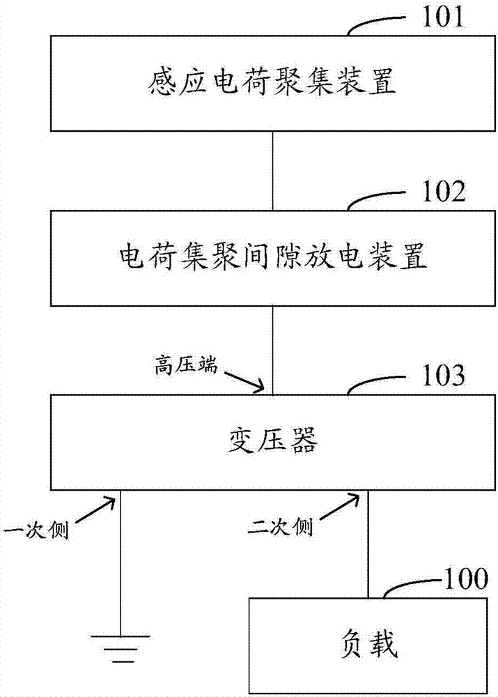
[0036] see figure 1 As shown, in one of the embodiments, a power taking device for overhead transmission lines is provided. like figure 1 As shown, the overhead power transmission line power taking device in this embodiment includes: an induction charge accumulation device 101, a charge accumulation gap discharge device 102 and a transformer 103, one end of the charge accumulation gap discharge device 102 is connected to the induction charge accumulation device 101, and the charge accumulation The other end of the gap discharge device 102 is connected to the high volta...


PUM


Abstract

The invention relates to an overhead transmission line power pickup device and method. The overhead transmission line device comprises an inductive charge aggregation device, a charge aggregation gap discharge device and a transformer; one terminal of the charge aggregation gap discharge device is connected to the inductive charge aggregation device, and the other terminal of the charge aggregation gap discharge device is connected to a high voltage terminal of the transformer; a primary side of the transformer is connected to the ground; a secondary side of the transformer is connected to a load; the charge aggregation gap discharge device has a gas gap; the inductive charge aggregation device inducts and aggregates the charges in an electromagnetic field of the overhead transmission line; the charges aggregated by the inductive charge aggregation device intermittently breaks down the gas gap of the charge aggregation gap discharge device to form pulse current; and the pulse current is outputted to the load after regulation by the transformer. When being used for a non-contact online monitoring device, the overhead transmission line power pickup device and method can guarantee a non-contact online monitoring device to operate safely and stably.

Description

technical field [0001] The invention relates to the technical field of power grids, in particular to a device and method for taking power from an overhead transmission line. Background technique [0002] On the overhead transmission wire, an online monitoring device is generally installed on the line tower to monitor the transmission wire online. In order to ensure that the online monitoring device can be used for a long time, the power supply of the online monitoring device becomes a main problem affecting the available time of the online monitoring device. Although wireless power transfer (WPT) methods (respectively, inductive coupling, near-field resonance and microwave radiation) are widely used in small electrical equipment such as mobile phones and electric toothbrushes, but through the above-mentioned inductive coupling, When the three methods of near-field resonance and microwave radiation are used to supply power to online monitoring equipment, it is necessary to h...

Claims


Application Information

Patent Timeline
Patent Type & Authority Applications(China)
IPC IPC(8): H02J50/20H02H9/06
CPCH02H9/06
Inventor 苏超李海涛邝振星罗建军胡金磊
Owner QINGYUAN POWER SUPPLY BUREAU OF GUANGDONG POWER GRID CO LTD
Why Eureka
Try Eureka