Motor mounting rack used for machinery device

A motor mounting frame and mechanical equipment technology, applied in the direction of electromechanical devices, electrical components, electric components, etc., can solve the problems of poor motor installation stability, etc., and achieve the effects of strong installation stability, avoiding adverse effects, and good buffering effect

Inactive Publication Date: 2017-08-18
江先庆
View PDF1 Cites 0 Cited by
  • Summary
  • Abstract
  • Description
  • Claims
  • Application Information

AI Technical Summary

Problems solved by technology

[0005] A motor mounting frame for mechanical equipment proposed by the present invention solves the problem that there is an adverse effect between two motors in the working state, and the installation stability of the motor on the motor mounting frame is poor

Method used


Image

  • Motor mounting rack used for machinery device
  • Motor mounting rack used for machinery device
  • Motor mounting rack used for machinery device

Examples


Embodiment Construction

[0029] The technical solutions in the embodiments of the present invention will be clearly and completely described below in conjunction with the accompanying drawings in the embodiments of the present invention. Obviously, the described embodiments are only a part of the embodiments of the present invention, rather than all the embodiments.

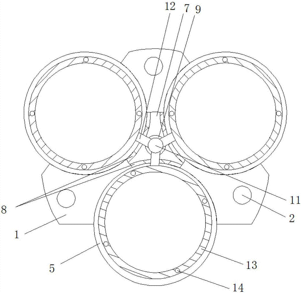
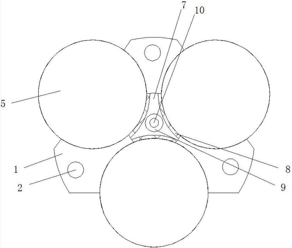
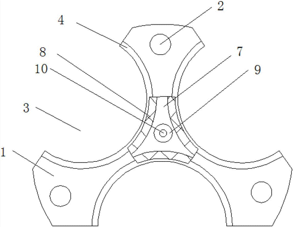
[0030] Reference Figure 1-6 , A motor mounting frame for mechanical equipment, including a triangular motor mounting frame body 1, one side triangle of the motor mounting frame body 1 is provided with mounting holes 2, and the center of the three sides of the motor mounting frame body 1 is opened There are semi-circular grooves 3 with openings on both sides. A fan-shaped mounting plate 4 is welded to the center of the side wall of each semi-circular groove 3, and a motor 5 is placed on one side of the three fan-shaped mounting plates 4. The fan-shaped mounting plate The other side of 4 is fixed by the first screw 6 to the motor 5, so that ...


PUM


Abstract

The invention belongs to the field of motor mounting frames for mechanical equipment, in particular to a motor mounting frame for mechanical equipment, aiming at the adverse effects existing between two motors in the working state, and the motor on the motor mounting frame For the problem of poor installation stability, the following scheme is now proposed, which includes a triangular main body of the motor mounting frame, one side triangle of the main body of the motor mounting frame is provided with mounting holes, and the central position of the three sides of the main body of the motor mounting frame is provided with two A semicircular slot with an opening is arranged on the side, and a fan-shaped mounting plate is welded at the center of the side wall of each semi-circular slot, and a motor is placed on one side of the three fan-shaped mounting plates, and the other side of the fan-shaped mounting plate passes through the first The screw fixes the motor. The present invention is economical and practical. There is a buffer structure between two adjacent motors, which avoids adverse effects between adjacent motors in the working state, and the installation of the motor on the main body of the motor mounting frame Greater stability.

Description

Technical field [0001] The invention relates to the technical field of a motor mounting frame for mechanical equipment, and in particular to a motor mounting frame for mechanical equipment. Background technique [0002] The motor is commonly known as "motor". The motor refers to an electromagnetic device that realizes the conversion or transmission of electrical energy according to the law of electromagnetic induction. Its main function is to convert electrical energy into mechanical energy. The motor is used as a power source in electrical appliances or various mechanical equipment. Motors have an extremely wide range of applications in mechanical equipment. When installing motors on mechanical equipment, a motor mounting frame is required. With the continuous development of science and technology, the types and shapes of motor mounting frames are becoming more and more. There are many, but the motor mounting frame generally can only install one motor. When a certain motor needs...

Claims


Application Information

Patent Timeline
Patent Type & Authority Applications(China)
IPC IPC(8): H02K5/00
CPCH02K5/00
Inventor 江先庆
Owner 江先庆
Why Eureka
Try Eureka