
Automatic rotor iron core assembling device and motor manufacturing equipment having same

A rotor core and assembly device technology, applied in the manufacture of stator/rotor body, etc., can solve the problems of reduced assembly efficiency and increased processing costs, and achieve the effect of precise circumferential positioning

Active Publication Date: 2017-08-18
尼得科智能装备(浙江)有限公司
View PDF7 Cites 2 Cited by
  • Summary
  • Abstract
  • Description
  • Claims
  • Application Information

AI Technical Summary

Problems solved by technology

In this scheme, the central shaft needs to be further processed to form key protrusions, and the center hole of each rotor core is further processed to form skewed key grooves, which increases the processing cost
In addition, during the assembly process, the relative rotation between the rotor and the central shaft is required to achieve the alignment position of the key protrusion and the skewed keyway, and the assembly efficiency is reduced

Method used


Image

  • Automatic rotor iron core assembling device and motor manufacturing equipment having same
  • Automatic rotor iron core assembling device and motor manufacturing equipment having same
  • Automatic rotor iron core assembling device and motor manufacturing equipment having same

Examples


Embodiment Construction

[0060] Reference will now be made in detail to various embodiments of the present invention, examples of which are illustrated in the accompanying drawings and described below. While the invention will be described in conjunction with exemplary embodiments, it will be appreciated that present description is not intended to limit the invention to those exemplary embodiments. On the contrary, the invention is intended to cover not only the exemplary embodiments but also various alternatives, modifications, equivalents and others, which may be included within the spirit and scope of the invention as defined by the appended claims. implementation plan. For ease of explanation and precise definition in the appended claims, the terms "upper," "lower," "inner," and "outer" are used to describe features of the exemplary embodiments with reference to their positions as shown in the drawings. to describe.

[0061] Exemplary embodiments of the present invention will be described in det...


PUM


Abstract

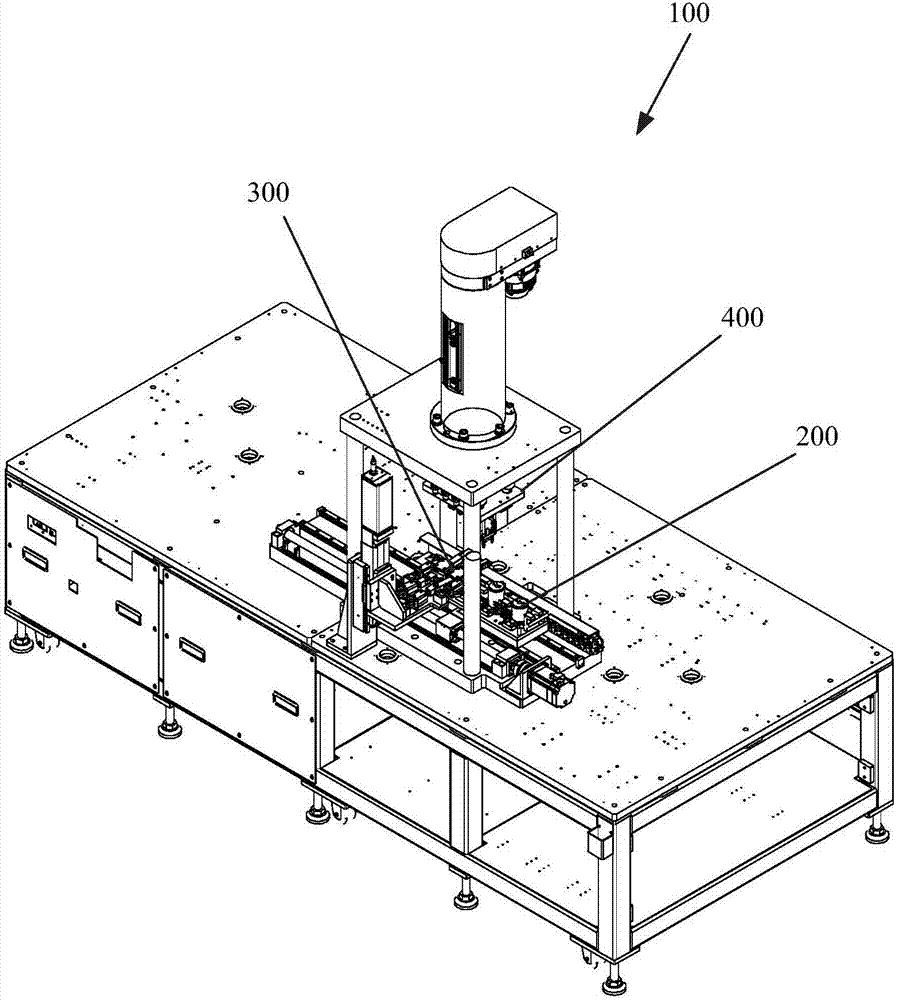
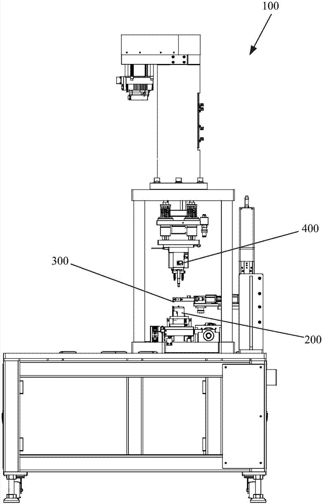
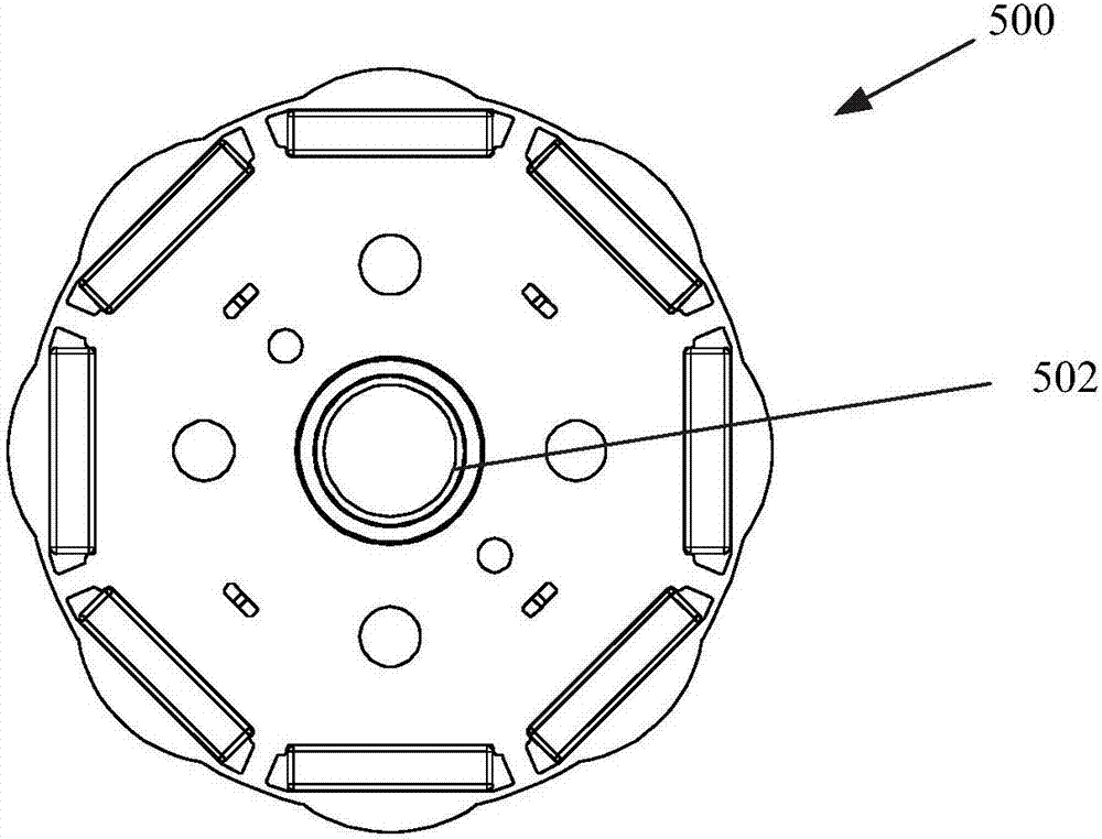
The invention relates to an automatic rotor iron core assembling device and motor manufacturing equipment having the same. The automatic rotor iron core assembling device comprises an insertion portion, a plurality of accommodating portions and a rotation portion; then insertion portion is used for inserting shafts into the center through holes of a plurality of rotor iron cores sequentially; the plurality of accommodating portions are use for accommodating rotor iron cores to be assembled; each of the accommodating portions is provided with a group of positioning protruding portions which extend out axially; each group of positioning protruding portions can be inserted into one group of circumferential positioning holes so as to circumferentially position a corresponding rotor iron core; the inner diameter of the circumferential positioning holes is larger than the outer diameter of the positioning protruding portions which are inserted into the circumferential positioning holes; the rotation portion is used for making the rotor iron cores arranged on the accommodating portions rotate with the center through holes of the rotor iron cores adopted as centers to positions where the outer peripheries of the positioning protruding portions abut against the inner peripheries of the positioning holes, and holding the rotor iron cores at the positions until the shafts are inserted into specified positions of the rotor iron cores; and the positions of each group of positioning protruding portions in the plurality of positioning protruding portions rotate to deviate by a specified angle relative to an adjacent group of positioning protruding portions.

Description

technical field [0001] The present invention generally relates to the assembly of a rotor core on a shaft in a motor, and more particularly relates to an automatic rotor core assembly device and a motor manufacturing equipment provided with the automatic rotor core assembly device. Background technique [0002] A reluctance motor is a well known type of synchronous motor. Normally, a coil for supplying alternating current at predetermined time phases is wound around a plurality of slots of the stator. The stator forms a rotating magnetic field. The rotor is rotatably supported inside the stator. The rotor has a rotor core. A plurality of rotor cores are stacked. Each rotor core has a plurality of magnetic poles. Skew angle so as to achieve the desired synchronous rotation can be position control and speed control. [0003] During the assembly process of motor rotor cores, it is usually necessary to assemble multiple rotor cores stacked on top of each other on the shaft, a...

Claims


Application Information

Patent Timeline
IPC IPC(8): H02K15/02
CPCH02K15/02
Inventor 肖慧
Owner 尼得科智能装备(浙江)有限公司
Learn More